
Operating instructions


Great Plains Manufacturing, Inc. Table of Contents Index Operating Instructions 17
2013-03-25 Table of Contents Index 403-362M
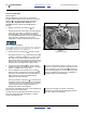
Fertilizer System Overview
Refer to Figure 6 on page 16
1. Hydraulic Fan:
The fan supplies air for both fertilizer and seed
delivery. Fan rpm is operator-adjusted via the tractor
circuit’s hydraulic flow control.
2. Fan RPM Sensor:
Fan rpm is measured by a sensor mounted inside
the fan cage, and reported on the seed monitor
console.
3. Butterfly Valve (Fertilizer Leg):
Manually-adjusted butterfly valves are provided on
the splitter at the fan outlet. The valve on the right leg
controls air for the fertilizer system. See page 19 for
valve adjustment.
4. Fertilizer Air Inlet Manifold:
Fan air is divided into six equal flows at the inlet
manifold.
5. Fertilizer Hopper:
The front hopper is the fertilizer hopper. See
“Loading Fertilizer” on page 12. The hopper
contains a ladder-style pressure-balancing system
(not shown) to help prevent fertilizer bridging.
6. Pressure Sensor:
A sensor in the fertilizer hopper reports air pressure
to the seed monitor, and is reported on the console.
7. Fertilizer Level Sensor:
The fertilizer hopper contains a level sensor. When
this sensor is exposed (fertilizer level below sensor),
approximately 78 liters (2.2 bu) of fertilizer remains.
8. Fertilizer Meter:
The fertilizer meter is at base of the fertilizer hopper.
There is no slide gate. The meter is always open to
the fertilizer hopper.
9. Meter Doors:
The meter box has doors at the bottom for clean-out
(front) and calibration (rear). See page 27 or
page 35. These doors are closed for field operations.
10. Fertilizer RPM Sensor (shaft monitor):
A sensor on the meter flute shaft reports shaft rate to
the seed monitor. The seed monitor does not report
material rate from this data, but can generate alarms
on shaft stoppages or rpm out-of-limits.
11. Range Gears:
Interchangeable Final Range Gears set the coarse
rate of the flute shaft. The meter system is powered
by a ground drive (not shown), which has a variable
rate gearbox for fine adjustment. See page 23.
Fertilizer metering occurs whenever the planter is
lowered and in forward motion.
12. Flute Stars:
Fertilizer is metered into the manifold air stream by
flutes on the final shaft. The four inside
compartments have three flutes (six halves) and feed
3-way towers. The two outside compartments have
two flutes and feed 2-way towers.
13. Fertilizer Manifold Outlets:
The fan airflow from the inlet manifold entrains
metered fertilizer in the chambers below the flutes,
and exits at the manifold outlets. Each outlet serves
a single hose to a single distribution tower, and
multiple rows.
The center four outlets serve 3-way towers.
The outside two outlets serve 2-way towers.
14. 3-way Tower:
Four of the six towers divide the air/fertilizer flow
3ways.
15. 2-Way Tower:
Two of the six towers (the two serving wing end
rows) divide the air/fertilizer flow 2 ways.
16. Vent for 2-Way Towers:
To balance the airflow at all manifold ports, the 2-way
towers vent some of the air at the tower inlet. See
page 43 for maintenance.
17. Blockage Detectors:
Each tower divider outlet is equipped with a material
sensor, connected to the seed monitor and
configured for “Blockage” mode. These report any
flow failure at the rows. See page 54.
18. Coulter Applicators:
Coulters are factory configured for side-dress
fertilizer application, at 5cm (2in) off-row, and a
depth of 5cm (2in), “zone” application. The coulter
has adjustments for depth and the height of the
applicator exit tube.
Material Mis-Application Risk:
If it is ever necessary to disconnect delivery hoses at the
manifold, it is essential that the hoses to the wing-end
(2-way) towers be connected to the outside ports
(#1 and #6) at the manifold.