
Operating instructions


18 YP2425F/YP4025F Table of Contents Index Great Plains Manufacturing, Inc.
403-362M Table of Contents Index 2013-03-25
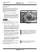
Fan Circuit Operation
Refer to Figure 7
Three hydraulic hoses serve the fan, and must be
properly connected for the fan to operate in the correct
direction , at recommended speeds, and without
damage. See “Hydraulic Hose Hookup” in the
401-406M (YP24) or 401-571M (YP40) Operator
manual.
1. Always connect the case drain line first.
This line protects the outer shaft seal of the hydraulic
motor. The case drain is a small line to the hitch,
provisioned with a specialized low-seep flat-face
case drain Quick Disconnect. Pressure spikes during
motor operation, and pressure cycles due to
temperature change are bled off by the case drain.
Motor Seal Damage Hazard
Do not apply pressure to the case drain line. Do not change the
special QD connector. A restricted or sealed case drain line
will promptly result in motor seal damage.
2. Connect the motor return line second, to sump.
The planter includes a 1
1
⁄
16
in low back-pressure QD
coupler set. Install the receptacle on a tractor sump
port, and not at a normal remote return port. The
unusual size aids in ensuring correct connection, so
that the motor return line handles high volume at low
back-pressure, ensuring full motor performance.
3. Connect the motor inlet line to a tractor remote
capable of 95 liters per minute (25 gpm). If a priority
remote is available, use it for the fan.
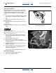
4. The fan hydraulic circuit includes a check valve ,
which provides a relief path for oil at motor shutoff.
If the fan is connected in reverse, flow through this
valve results in low fan rpm, providing strong
indication reversed connection.
Correct fan direction is shown at . If reversed fan is
suspected, observe it during shutoff, as the direction
of motion is easier to see at lower rpms as it slows to
a stop (initial startup is virtually instantaneous,
making observation at start difficult).
Fan speed is controlled by the tractor circuit and butterfly
valves (and not the seed monitor).
You may stop the fan by setting the circuit to neutral or
float. The check valve slows the blades to a stop by
locally recirculating the oil.
Figure 7
Hydraulics at Fan
31095
2
3
4
5
1
1
2
3
If the fan is connected in reverse, it may not run at all
(due to no oil source at the return connection). If oil is
present, oil bypass at the check valve prevents the
fan from reaching high rpm. A reversed fan may send
some air to the delivery systems, but is incapable of
providing reliable air flow for planting.
5
4
5
1
Fan speed can change as oil heats to operating
temperature. Re-check fan rpm and hopper pressure
more often during early operations.