
Operating instructions


20 YP2425F/YP4025F Table of Contents Index Great Plains Manufacturing, Inc.
403-362M Table of Contents Index 2013-03-25
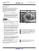
Monitor Operation
The YP2425F-2470, YP4025F-1630 and YP4025F-1670
includes the standard DICKEY-john
®
IntelliAg
®
monitor,
operating in Planter/Drill Control mode. There are setup
differences vs. other YP40 planters, generally:
• Row delivery tubes are equipped with blockage
sensors. These rows are treated as “seed” rows
numbered from
• Seed tubes are monitored in Population mode.
Fertilizer applicators are monitored in Blockage mode.
• There are two hopper level sensors in use:
1. Seed air box
2. Fertilizer hopper level
• There is one air pressure sensor in use, installed in
the fertilizer hopper.
• There is a second
a
rpm sensor, installed on the left
end of the fertilizer meter shaft. Although the seed
monitor can report the rpm, the main use is as a shaft
monitor.
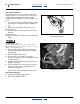
Set upper and lower rpm limits based on the fertilizer
rate chart, and your planned field speed. The chart
shows expected meter rpm for various gearbox
settings, in High and Low range, at 9.7 kph (6 mph). If
using a different field speed, adjust the expected rpm
proportionately.
Marker Operation
The YP24/YP40 DF/seeder feature does not affect
marker operations.
YP24 YP40
25 (actual seed row 1) to 17 (actual seed row 1) to
48 (actual seed row 24) 32 (actual seed row 16)
Note: Fertilizer is not set up as a separate Material or
Channel. The monitor’s “GRAN FERT” air drill
mode is not used. The seed monitor is not
engaged for fertilizer calibration, and no
“CAL CONST” is required.
Note: There is no optional level sensor for the seed
hopper.
a. The first rpm sensor is on the hydraulic motor for the seed meters.