
Operating instructions


56 YP2425F/YP4025F Table of Contents Index Great Plains Manufacturing, Inc.
403-362M Table of Contents Index 2013-03-25
Planter Control Channel Setup
(Controlled Hydraulic Drive)
25. At the Control Setup screen, press the Channel
Setup button .
26. Select Channel 1 and verify that the channel is set to
Planter Control.
27. Enter desired values using Table as reference.
28. After planter control setup, calibrate hydraulic valve
by pressing the Valve Cal button .
29. Ensure implement is raised. With brakes locked and
transmission in PARK position, start engine.
30. Engage hydraulics and run engine at normal speed
until hydraulic fluid is at operating temperature.
31. Verify point row clutches are turned ON.
Equipment Damage Risk:
Do NOT perform the next step unless meters are installed in all
locations across planter row units or drive damage may occur.
32. Press the START button . Turn the master switch
to the ON position.
33. The valve calibration starts immediately. Keep the
hydraulics engaged until the calibration completes.
34. When the screen indicates calibration is complete,
press the Channel Setup button to return to
Channel 1 home screen.
35. Turn the master switch OFF.
36. To set up additional control channels (planter or
fertilizer control), press the Next Channel button .
37. Press the Work Screen button when channel
configurations are complete to return to the Main
Work screen.
Once a control channel has been established as Planter
Control, any new materials established as Planter
Control on the Material Setup screen are automatically
added as optional materials for Planter Control channels
on the Control Setup screen.
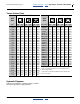
Planter Control Setup
Default
Value or
Value to
Enter
Instructions/Definitions
Type Planter
Control
Set desired Channel Type as
Planter Control.
Material
Name
Displays only materials that
have been configured for the
channel type.
Control
Mode
AUTO
Auto is used in normal
operating conditions
calculating the rate of how the
system is running. Manual
mode acts as an override if
application rate sensors are
inoperable allowing the use of
increase/decrease buttons to
set the fl ow rate for the
control. Refer to System
Configuration section of PDC
Operator manual for additional
information.
Drive
Type PWM
A hydraulic valve varies the oil
flow to the motor proportioned
to the electric current supplied.
Drive
Frequen
cy
100 Hz
If not using a DICKEY-john
supplied valve, see the
manufacturer’s specifications
for drive frequency.
Input
Filter 50
Feedback frequency filter for
the control channel. DO NOT
CHANGE.
Gear
Ratio
1.900
Specifies the actual ratio from
the feedback sensor to the
seed meter shaft RPM.
Number of revolutions the
feedback sensor turns in
relation to one revolution the
seed meter turns.
Sensor
Constan
t
360
Sensor Constant establishes
the number of pulses for one
revolution of the feedback
sensor. If a DICKEY-john
application rate sensor is
used, the value should be set
to 360.0.
# of
Seed
Rows
Entry of a specific number of
seed rows for the control
channel. Row assignment is