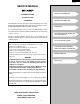
R - 370EK R - 3 70 E S SERVICE MANUAL S4112R370EPS/ MICROWAVE OVEN Popcorn Baked Fresh Potatoes Vegetables Reheat Sensor Ground Frozen Meat Vegetables Chicken Breast Rice Frozen Entree Rolls & Muffins MODELS Compu Defrost Fish Seafood Veverage Kitchen Timer Clock 1 2 3 4 5 Power Level Custom Help 6 7 8 9 0 STOP Clear Minute Plus START R-370EK R-370ES In the interest of user-safety the oven should be restored to its original condition and only parts identical to those specified sho
R-370EK R- 370ES PRECAUTIONS TO BE OBSERVED BEFORE AND DURING SERVICING TO AVOID POSSIBLE EXPOSURE TO EXCESSIVE MICROWAVE ENERGY (a) Do not operate or allow the oven to be operated with the door open.
R-370EK R-370ES WARNING TO SERVICE PERSONNEL Microwave ovens contain circuitry capable of producing very high voltage and current, contact with following parts may result in a severe, possibly fatal, electrical shock. (Example) High Voltage Capacitor, High Voltage Power Transformer, Magnetron, High Voltage Rectifier Assembly, High Voltage Harness etc.. Read the Service Manual carefully and follow all instructions. Don't Touch ! Danger High Voltage When the testing is completed, 1.
R- 370EK R- 37 0ES MICROWAVE MEASUREMENT PROCEDURE A. Requirements: 1) Microwave leakage limit (Power density limit): The power density of microwave radiation emitted by a microwave oven should not exceed 1mW/cm2 at any point 5cm or more from the external surface of the oven, measured prior to acquisition by a purchaser, and thereafter (through the useful life of the oven), 5 mW/cm2 at any point 5cm or more from the external surface of the oven.
R-370EK R-370ES SERVICE MANUAL PRODUCT DESCRIPTION MICROWAVE OVEN R-370EK/ R-370ES GENERAL INFORMATION FOREWORD This Manual has been prepared to provide Sharp Electronics Corp. Service Personnel with Operation and Service Information for the SHARP MICROWAVE OVEN, R-370EK, R-370ES. It is recommended that service personnel carefully study the entire text of this manual so that they will be qualified to render satisfactory customer service. Check the interlock switches and the door seal carefully.
R- 370EK R- 37 0ES SPECIFICATION ITEM DESCRIPTION Power Requirements 120 Volts / 13.5 Amperes 60 Hertz Single phase, 3 wire grounded Power Output 1000 watts (IEC TEST PROCEDURE) Operating frequency of 2450MHz Case Dimensions Width 17-1/4" Height 13-3/8" Depth 18-3/8" Cooking Cavity Dimensions Width 13-3/4" Height 7-1/4" Depth 16-1/2" 1.4 Cubic Feet Control Complement Touch Control System Clock ( 1:00 - 12:59 ) Timer (0 - 99 min.
R-370EK R-370ES contact a qualified electrician and have it replaced with a properly grounded three-pronged wall receptacle or have a grounding adapter properly grounded and polarized. If the extension cord must be used, it should be a 3-wire, 15 amp. or higher rated cord. Do not drape over a countertop or table where it can be pulled on by children or tripped over accidentally. CAUTION: DO NOT UNDER ANY CIRCUMSTANCES CUT OR REMOVE THE ROUND GROUNDING PRONG FROM THIS PLUG.
R- 370EK R- 37 0ES OPERATION DESCRIPTION OF OPERATING SEQUENCE The following is a description of component functions during oven operation. so that it will function in the following sequence. (1) When the door opens from the closed position, the secondary interlock relay (RY2) and primary interlock switch open their contacts. And contacts of the relay (RY1) remains closed. Then the monitor switch contacts close. (2) When the door is closed from the open position, the monitor switch contacts open first.
R-370EK R-370ES is cooked, water vapor is developed. The sensor “senses” the vapor and its resistance increases gradually. When the resistance reaches the value set according to the menu, supplementary cooking is started. The time of supplementary cooking is determined by experiment with each food category and inputted into the LSI. An example of how sensor works: (POTATOES) 3. Sensor detects moisture and humidity and calculates cooking time and variable power. Cooking Sequence. 1.
R- 370EK R- 37 0ES SCHEMATIC NOTE: CONDITION OF OVEN 1. DOOR CLOSED 2. CLOCK APPEARS ON DISPLAY NOTE: " " indicates components with potential above 250V. AH SENSOR MONITOR FUSE 20A OVEN THERMAL CUT-OUT MG. THERMAL CUT-OUT POWER TRANSFORMER N.O. F3 F2 F1 SECONDARY INTERLOCK RELAY (RY2) CAPACITOR 0.94µF AC 2200V COM. GRN B2 120V AC 60 Hz MONITOR SWITCH CONTROL UNIT B1 DOOR SENSING SWITCH OL OVEN LAMP RELAY (RY1) N.O.
R-370EK R-370ES DESCRIPTION AND FUNCTION OF COMPONENTS DOOR OPEN MECHANISM RELAY (RY1), PRIMARY INTERLOCK SWITCH AND MONITOR SWITCH FOR PROPER OPERATION. (REFER TO CHAPTER "TEST PROCEDURE"). NOTE: MONITOR FUSE AND MONITOR SWITCH ARE REPLACED AS AN ASSEMBLY. The door is opened by pulling the door. Refer to the Figure D-1.
R- 370EK R- 37 0ES TROUBLESHOOTING GUIDE Never touch any part in the circuit with your hand or an uninsulated tool while the power supply is connected. When troubleshooting the microwave oven, it is helpful to follow the Sequence of Operation in performing the checks. Many of the possible causes of trouble will require that a specific test be performed. These tests are given a procedure letter which will be found in the "Test Procedure "section.
R-370EK R-370ES CK = Check / RE = Replace Monitor fuse blows when power cord is plugged into wall receptacle. OFF CONDITION Any letters or indicators do not appear in display when power cord is first plugged into wall outlet. Display does not operate properly when STOP/CLEAR key is touched. (Buzzer should sound and ":" or time of day should appear in display.) Oven lamp does not light when door is opened. Oven lamp does not go out when door is closed.
R- 370EK R- 37 0ES TEST PROCEDURES PROCEDURE LETTER A COMPONENT TEST MAGNETRON ASSEMBLY TEST 1. 2. 3. 4. 5. 6. 7. 8. 9. Disconnect the power supply cord, and then remove outer case. Open the door and block it open. Discharge the high voltage capacitor. To test for an open filament, isolate the magnetron from the high voltage circuit. A continuity check across the magnetron filament leads should indicate less than 1 ohm.
R-370EK R-370ES TEST PROCEDURES PROCEDURE LETTER COMPONENT TEST (HIGH VOLTAGES ARE PRESENT AT THE HIGH VOLTAGE TERMINAL, SO DO NOT ATTEMPT TO MEASURE THE FILAMENT AND HIGH VOLTAGE.) C HIGH VOLTAGE RECTIFIER TEST 1. 2. 3. 4. Disconnect the power supply cord, and then remove outer case. Open the door and block it open. Discharge the high voltage capacitor. Isolate the rectifier from the circuit.
R- 370EK R- 37 0ES TEST PROCEDURES PROCEDURE LETTER COMPONENT TEST 5. Reconnect all leads removed from components during testing. 6. Reinstall the outer case (cabinet). 7. Reconnect the power supply cord after the outer case is installed. 8. Run the oven and check all functions. CAUTION: IF THE THERMAL CUT-OUT INDICATES AN OPEN CIRCUIT AT ROOM TEMPERATURE, REPLACE THERMAL CUT-OUT. F PRIMARY INTERLOCK SWITCH TEST 1. 2. 3. 4. 5. 6. 7. 8. Disconnect the power supply cord, and then remove outer case.
R-370EK R-370ES TEST PROCEDURES PROCEDURE LETTER COMPONENT TEST 5. 6. 7. 8. actuator is pushed by a screw driver through the lower latch hole on the front plate of the oven cavity with the door opened (in this condition the plunger of the monitor switch is pushed in), the meter should indicate an open circuit. If improper operation is indicated, the switch may be defective.
R- 370EK R- 37 0ES TEST PROCEDURES PROCEDURE LETTER COMPONENT TEST If the Key unit is defective, replace the key unit. 2. Control Unit The following symptoms indicate a defective control unit. Before replacing the control unit, perform the Key unit test (Procedure J) to determine if control unit is faulty. 2-1 In connection with pads. a) When touching the pads, a certain group of pads do not produce a signal. b) When touching the pads, no pads produce a signal.
R-370EK R-370ES TEST PROCEDURES PROCEDURE LETTER K COMPONENT TEST RELAY TEST 1. 2. 3. 4. 5. Disconnect the power supply cord, and then remove outer case. Open the door and block it open. To discharge the high voltage capacitor, wait for 60 seconds. Disconnect the leads to the primary of the power transformer. Ensure that these leads remain isolated from other components and oven chassis by using insulation tape. 6. After that procedure, re-connect the power supply cord. 7.
R- 370EK R- 37 0ES TEST PROCEDURES PROCEDURE LETTER COMPONENT TEST STEPS OCCURRENCE CAUSE OR CORRECTION 1 Only pattern at "a" is broken. *Insert jumper wire J1 and solder. 2 Pattern at "a" and "b" are broken. *Insert the coil RCILF2003YAZZ between "c" and "d". RY1 5) Make a visual inspection of the varistor. Check 1 2 for burned damage and examine the transformer with a tester for the presence of layer short-circuit (check the primary coil resistance which is approximately 212Ω ± 10%).
R-370EK R-370ES TEST PROCEDURES PROCEDURE LETTER COMPONENT TEST (5) Be sure the exterior of the cooking container and the interior of the oven are dry. Wipe off any moisture with a dry cloth or paper towel. (6) The Sensor works with food at normal storage temperature. For example, chicken pieces would be at refrigerator temperature and canned soup at room temperature. (7) Avoid using aerosol sprays or cleaning solvents near the oven while using Sensor settings.
R- 370EK R- 37 0ES TEST PROCEDURES PROCEDURE LETTER COMPONENT TEST (8) After that procedure, re-connect the power supply cord. (9) Check the sensor cook operation proceed as follows: 9-1. Touch the KITCHEN TIMER/CLOCK pad once, the POWER LEVEL pad twice, the START pad once, the number pad 1 once and the number pad 4 once. 9-2. The control panel is in the sensor cooking operation. 9-3. After approximately 25 seconds, push plunger of select switch for more than 3 seconds.
R-370EK R-370ES TOUCH CONTROL PANEL ASSEMBLY OUTLINE OF TOUCH CONTROL PANEL In addition, the synchronizing signal is available in order to compose a basic standard time in the clock circuit. The control unit section consists of the following units. (1) Key Unit (2) Control Unit (The Control Unit consists of Power Unit and CPU Unit). The principal functions of these units and the signals communicated among them are explained below.
R- 370EK R- 37 0ES Pin No. Signal I/O Description 9 AN1 IN AH sensor input. This input is an analog input terminal from the AH sensor circuit, and connected to the A/D converter built into the LSI. 10 AN0 IN Used for initial balancing of the bridge circuit (absolute humidity sensor). This input is an analog input terminal from the AH sensor circuit, and connected to the A/D converter built into the LSI.
R-370EK R-370ES Pin No. Signal I/O Description 31 XOUT OUT 32 VSS IN 33 P27 OUT Terminal not used. 34 P26 OUT Key strobe signal. Signal applied to touch-key section. A pulse signal is input to P43-P46 terminal while one of G7 line keys on key matrix is touched. 35 P25 OUT Key strobe signal. Signal applied to touch-key section. A pulse signal is input to P43-P46 terminal while one of G6 line keys on key matrix is touched. 36 P24 OUT Key strobe signal.
R- 370EK R- 37 0ES ABSOLUTE HUMIDITY SENSOR CIRCUIT 1) Structure of Absolute Humidity Sensor The absolute humidity sensor includes two thermistors as shown in the illustration. One thermistor is housed in the closed vessel filled with dry air while another in the open vessel. Each sensor is provided with the protective cover made of metal mesh to be protected from the external airflow.
R-370EK R-370ES TOUCH CONTROL PANEL SERVICING transformer. 4) Re-install the outer case (cabinet). 5) Re-connect the power supply cord after the outer case is installed. 6) Run the oven and check all functions. A. On some models, the power supply cord between the touch control panel and the oven itself is so short that the two can’t be separated. For those models, check and repair all the controls (sensor-related ones included) of the touch control panel while keeping it connected to the oven. B.
R- 370EK R- 37 0ES COMPONENT REPLACEMENT AND ADJUSTMENT PROCEDURE WARNING AGAINST HIGH VOLTAGE: Microwave ovens contain circuitry capable of producing very high voltage and current, contact with following parts may result in severe, possibly fatal, electric shock. (Example) High Voltage Capacitor, Power Transformer, Magnetron, High Voltage Rectifier Assembly, High Voltage Harness etc.. WARNING: Avoid possible exposure to microwave energy. Please follow the instructions below before operating the oven. 1.
R-370EK R-370ES 6. Lift entire outer case from the unit. CAUTION: 1. DISCONNECT OVEN FROM POWER SUP PLY BEFORE REMOVING OUTER CASE. 2. DISCHARGE THE HIGH VOLTAGE CAPACITOR BEFORE TOUCHING ANY OVEN COMPONENTS OR WIRING. NOTE: When replacing the outer case, the 2 special Torx screws must be reinstalled in the same locations.
R- 370EK R- 37 0ES transformer from the high voltage capacitor. 6. Remove one (1) screw holding capacitor holder to base plate. 7. Remove one (1) screw holding high voltage rectifier assembly to capacitor holder. 8. Disconnect rectifier terminal from the capacitor. High voltage rectifier assembly is now free. 9. Remove the capacitor holder. The capacitor is now free.
R-370EK R-370ES fan blade. 5. Install the fan blade to the shaft of fan motor by pushing the fan blade with a small, light weight, ball peen hammer or rubber mallet. CAUTION: * Do not hit the fan blade strongly when installed because the bracket may be disfigured. * Make sure that the fan blade rotates smooth after installation. * Make sure that the axis of the shaft is not slanted. 6. Catch two holes of fan duct on two tabs of the base plate. 7.
R- 370EK R- 37 0ES 8. Now the turntable motor is free. 9. After replacement use the one (1) screw to fit the turntable motor cover. CAUTION: NO SHARP EDGES MUST BE EVIDENT AFTER REMOVAL OF THE TURNTABLE MOTOR COVER. DOOR SENSING SWITCH/PRIMARY INTERLOCK SWITCH AND MONITOR SWITCH REMOVAL Reinstallation 1. Re-install each switch in its place. The primary interlock/ monitor switches are in the lower position and the door sensing switch is in the upper position. 2. Re-connect wire leads to each switch.
R-370EK R-370ES Note: The door on a microwave oven is designed to act as an electronic seal preventing the leakage of microwave energy from oven cavity during cook cycle. This function does not require that door be air-tight, moisture (condensation)-tight or light-tight. Therefore, occasional appearance of moisture, light or sensing of gentle warm air movement around oven door is not abnormal and do not of themselves indicate a leakage of microwave energy from oven cavity.
R- 370EK R- 37 0ES INDIVIDUAL DOOR PARTS REMOVAL PWB Cover DOOR PANEL 1. Disconnect the power supply cord. 2. Remove the door from the oven. Refer to "DOOR REPLACEMENT". 3. To discharge the high voltage capacitor, wait for 60 seconds. 4. The choke cover should have been removed. 5. Remove the four (4) screws holding the door panel to the door screen. 6. Now, door panel is free. Door frame CPU unit Hole of PWB cover 9-pin wire harness Tab of LCD holder Figure C-9(a).
1 2 3 33 4 5 WHT 9 PPL 7 GRY 8 BLU 6 GRN 5 1 CN-B 2 3 CN-F CN-C 1 9 CN-B 1 GRN 2 9-PIN WIRE HARNESS AH SENSOR BLK MONITOR FUSE & HOLDER 3 GRY CN-F 1 BLK 2 RED 3 WHT WHT BLK 9 W H T 8 7 G P R P Y L CN-C 6 B L U 5 G R N 9 CN-C 1 IC1 1 B R N (on the door) 4 3 2 Y O R L R E W G D CPU UNIT CN-G RED RED Figure S-1. Pictorial Diagram FAN MOTOR WHT GRY RED BLK WHT WHT N.C. 6 WHT WHT WHT BLK ORG RED THERMAL CUT-OUT (MG) OVEN LAMP WHT 5 COM.
R- 370EK R- 37 0ES 2 1 4 3 6 5 A A T1 – ZD1 HZ16-1 – GND C2 VA C3 INT C4 OVEN LAMP TURNTABLE MOTOR FAN MOTOR C6 BUZZER C5 MICRO C7 DOOR SENSING SWITCH C9 AHR C8 AHA Q1 2SB1238 R2 330 1w C – c COM + D22 1SS270A R4 3.3k Q21 DTD143ES RY1 N.O AC(H) C C21 10µ/35v D21 1SS270A N.O AC(N) OVEN LAMP TURNTABLE MOTOR FAN MOTOR D + SP1 PKM22EPT COM MICRO RY2 D Q22 DTA143ES B-2 DOOR SENSING SWITCH D20 1SS270A D40 1SS270A E B C1 C3 10µ/35v b + R1 2.
3 35 C7 DOOR SENSING SWITCH NOTE C5 C4 C6 C9 C8 C3 C2 MICRO OVEN LAMP TURNTABLE MOTOR FAN MOTOR BUZZER AHR AHA INT VA R9 680 1/2w LD1 LD2 LD3 LD4 4 R40 4.7k C1 0.1µ/50v R20 1k C20 0.1µ/50v : IF NOT SPECIFIED, 1/16W ± 5% R41 15k Q20 DTA143EKA Q30 DTA143EKA Q10 DTA143EKA C10 0.1µ /50v R1 82 Q1 2SA1037AK – A B R50 15k D50 MA152WA C3 0.01µ/25v R57 37.4kF R10 15k C D (J12) (J13) 4.7k (J10) (J11) 4.7k CF1 CSTS4.
R- 370EK R- 37 0ES 2 1 4 3 5 6 A A F DIP B R52 9 1 CN - C 2 B 1 R50 C51 D40 R51 CN - B C50 4 5 1 D20 3 IC2 1 Q1 E (R3) B B D C2 D21 1 Q21 (ZD2) (Q2) E SP1 2 (J2) OM E C1 VRS1 (J1) DU RY1 E CN - A ZD1 E B D E B R4 C21 1 2 Q22 C C3 R1 R53 R54 8 R2 CN - F C 7 1 S P F F D3 3 D1 4 T1 DU RY2 G OM G D22 D2 D4 H H Figure S-4.
R - 370EK R - 3 70 E S PARTS LIST Note: The parts marked “∆” may cause undue microwave exposure. The parts marked “*” are used in voltage more than 250V. REF. NO. PART NO.
R- 370EK R-370ES REF. NO. 4- 9 4-10 4-11 4-12 4-13 4-14 4-15 4-16 4-17 4-18 4-19 4-20 4-21 4-22 4-23 4-24 4-25 4-26 4-27 4-28 4-29 4-30 4-31 PART NO.
R - 370EK R - 3 70 E S HOW TO ORDER REPLACEMENT PARTS To have your order filled promptly and correctly, please furnish the following information. 1. MODEL NUMBER 2. REF. NO. 3. PART NO. 4. DESCRIPTION Order Parts from the authorized SHARP parts Distributor for your area. Defective parts requiring return should be returned as indicated in the Service Policy.
R- 370EK R-370ES 2 1 4 3 6 5 OVEN AND CABINET PARTS 7-13 4-17 2-4 A 7-17 4-28 A 7-14 1-14 7-4 4-18 7-8 4-28 4-26 B B 6-6 1-13 4-25 4-24 1-1 7-14 4-27 7-12 4-19 C C 6-5 7-13 7-7 7-11 4-6 4-21 1-9 4-23 7-11 D D 4-9 7-9 7-15 4-22 7-3 4-31 4-16 7-1 7-11 4-30 1-4 4-15 7-7 4-11 4-4 4-5 7-2 7-1 1-12 E E 1-11 2-2 7-1 4-8 1-3 4-1 7-7 1-8 1-5 7-5 7-1 x2 4-3 1-2 7-7 2-5 4-4 x2 1-8 7-3 4-12 1-4 F 4-14 7-5 7-10 F 1-3 7-7 7-6 7-3 4-20 7-7 3-1 1-10
R - 370EK R - 3 70 E S 2 1 4 3 6 5 A A DOOR PARTS 5-10 5-13 5-11 5-9 5-13 5-12 B 4-7 5-6 5-7 B 5-12 5-2 5-14 5-6 5-8 5-1 5-12 5-3 C C 5-3-1 5-12 D D 5-4 5-3-2 5-5 MISCELLANEOUS E E 6-3 6-8 6-4 (CAPACITOR) F F 6-9 Actual wire harness may be different from illustration.
R- 370EK R-370ES COPYRIGHT © 2001 BY SHARP CORPORATION ALL RIGHTS RESERVED. No part of this publication may be reproduced, stored in retrieval systems, or transmitted in any form or by any means, electronic, mechanical, photocopying, recording, or otherwise, without prior written permission of the publisher. 2001 SHARP CORP. (4S2.530E) Printed in U.S.