
Service manual


21
R-370EK
R-370ES
TOUCH CONTROL PANEL ASSEMBLY
OUTLINE OF TOUCH CONTROL PANEL
The control unit section consists of the following units.
(1) Key Unit
(2) Control Unit (The Control Unit consists of Power Unit and
CPU Unit).
The principal functions of these units and the signals com-
municated among them are explained below.
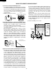
Key Unit
The key unit is composed of a matrix, signals generated in
the LSI are sent to the key unit through P20, P21, P22, P23,
P24, P25 and P26.
When a key pad is touched, a signal is completed through
the key unit and passed back to the LSI through P43, P44,
P45 and P46 to perform the function that was requested.
Control Unit
Control unit consists of LSI, ACL circuit, indicator circuit,
power source circuit, relay circuit, buzzer circuit, synchro-
nizing signal circuit, back light circuit and absolute humidity
sensor circuit.
1) ACL
This circuit generates a signal which resets the LSI to the
initial state when power is supplied.
2) Indicator Circuit
This circuit consists of 25 segments and 4 common
electrodes using a Liquid Crystal Display.
3) Power Source Circuit
This circuit generates voltages necessary in the control
unit from the AC line voltage.
In addition, the synchronizing signal is available in order
to compose a basic standard time in the clock circuit.
Symbol Voltage Application
VC -5V LSI(IC1)
4) Relay Circuit
A circuit to drive the magnetron, fan motor, turntable
motor and light the oven lamp.
5) Buzzer Circuit
The buzzer is responsive to signals from the LSI to emit
audible sounds (key touch sound and completion sound).
6) Synchronizing Signal Circuit
The power source synchronizing signal is available in
order to compose a basic standard time in the clock
circuit.
It accompanies a very small error because it works on
commercial frequency.
7) Door Sensing Switch
A switch to “tell” the LSI if the door is open or closed.
8) Back Light Circuit
A circuit to drive the back light (Light emitting diodes
LD1- LD4).
9) Absolute Humidity Sensor Circuit
This circuit detects moisture of the cooking food to allow
its automatic cooking.
LSI(IXA102DR)
The I/O signal of the LSI(IXA102DR) is detailed in the following table.
Pin No. Signal I/O Description
1-2 VL2-VL1 IN Power source voltage input terminal.
Standard voltage for LCD.
3-6 AN7-AN4 IN Terminal to change cooking constant according to the Model.
By using the A/D converter contained in the LSI, DC voltage in accordance with the Model
in operation is applied to set up its cooking constant.
7 AN3 OUT Back light circuit (Light emitting diodes) driving signal.
8 AN2 IN To input signal which communicates the door open/close information to LSI.
Door close "H" level signal (0V). Door open "L" level signal (-5V).