
Specifications


4
A39199, SM-SEARTEC R390H(S) O_M
INSTALLATION INSTRUCTIONS
1. Remove all packing materials from the oven cavity and the feature sticker from the oven door panel (if available).
Check the unit for any damage, such as a misaligned door, damaged door seals around the door or dents inside
the oven cavity or on the door. If there is any damage, please do not operate the oven until it has been checked
by a SERVICE CENTRE APPROVED BY SHARP and repaired, if necessary.
2. Accessories provided
1) Turntable 2) Roller Stay 3) Operation manual and cooking guide
3. Locate the roller stay in the centre of the oven, then fit the turntable on the roller stay. Make sure the turntable
and roller stay are centrally located and locked together. Refer to OVEN DIAGRAM below. NEVER operate
the oven without the roller stay and turntable.
4. The oven should not be installed in any area where excessive heat and steam are generated, for example,
next to a conventional oven unit.
The oven should be installed so as not to block ventilation openings.
Allow space of at least 15cm from top of the oven for air ventilation.
This oven is not designed to be built-in to a wall or cabinet.
5. Neither the manufacturer nor the distributors can accept any liability for damage to the machine or personal
injury for failure to observe the correct electrical connecting procedure.
The A.C. voltage and frequency must be single phase 220V, 50Hz.
6. WARNING - THIS APPLIANCE MUST BE EARTHED.
If the socket outlet in your house is not compatible with the pulg supplied, cut-off the mains plug and fit an
appropriate type, observing the wiring cord below.
If you are unsure how to do this get help from an electrician.
IMPORTANT - The wires in the power supply cord are coloured in accordance with the following cord:
Green-and-yellow : Earth
Blue : Neutral
Brown : Live
As the colours of the wires in the power supply cord of this appliance may not correspond with the coloured
marking identifying the terminals in your plug, proceed as follows:
The wire which is coloured green-and-yellow must be connected to the terminal in the plug which is marked
with the letter E or by the earth symbol
or coloured green or green-and-yellow.
The wire which is coloured blue must be connected to the terminal which is marked with the letter N or
coloured blue.
The wire which is coloured brown must be connected to the terminal which is marked with the letter L or
coloured brown.
Make sure the terminal screws are properly tightened and the power supply cord is held tightly by the cable
grip where it enters the plug.
NOTE: Under no circumstances should the cut-off plug be inserted into a socket outlet as a serious electric
shock may occur.
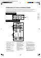
OVEN DIAGRAM
8. Waveguide cover (Do not remove)
9. Control panel (See page 5)
10. Liquid crystal display
11. Ventilation openings
12. Power supply cord
13. Rating plate
14. Turntable
15. Roller stay
1. Door open button
2. Oven lamp
3. Door hinges
4. Door safety latches
5. See through door
6. Door seals and sealing surfaces
7. Coupling