
Service manual


R-3S68
5
FUNCTION OF IMPORTANT COMPONENTS
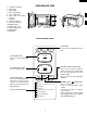
DOOR OPEN MECHANISM
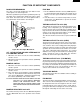
The door is opened by pushing the open button on the
control panel, refer to the Figure D-1.
When the open button is pushed, the open button pushes up
the switch lever, and then the switch lever pushes up the
latch head. The latch heads are moved upward and re-
leased from latch hook. Now the door will open.
LATCH
HEADS
LATCH HOOK
2ND. INTERLOCK
RELAY CONTROL
SWITCH
MONITOR
SWITCH
SWITCH
LEVER
1ST. LATCH
SWITCH
Figure D-1. Door Open Mechanism
1ST. LATCH SWITCH AND 2ND. INTERLOCK RE-
LAY CONTROL SWITCH
1. When the oven door is closed, the contacts COM-NO)
must be closed.
2. When the oven door is opened, the contacts .(COM-NO)
must be opened.
MONITOR SWITCH
1. When the oven door is closed, the contacts (COM-NC)
must be opened.
2. When the oven door is opened, the contacts (COM-NC)
must be closed.
3. If the oven door is opened and the contacts (COM-NO)
of the 1st. latch switch and 2nd. interlock relay fail to
open, the fuse M8A blows simultaneously with closing
the contacts (COM-NC) of the monitor switch.
CAUTION: BEFORE REPLACING A BLOWN FUSE M8A
TEST THE 1ST. LATCH SWITCH, MONITOR
SWITCH, 2ND. INTERLOCK RELAY, 2ND.
INTERLOCK RELAY CONTROL SWITCH AND
MONITOR RESISTOR FOR PROPER OPERA-
TION.
MONITOR RESISTOR R 0.8Ω 20W
The monitor resistor prevents the fuse M8A bursting when
the fuse M8A blows due to the operation of the monitor
switch.
FUSE M8A
1. The fuse M8A blows when the contacts (COM-NO) of the
1st. latch switch and 2nd. interlock relay remain closed
with the oven door open and when the monitor switch
closes.
2. If the wire harness or electrical components are short-
circuited, this fuse M8A blows to prevent an electric
shock or fire hazard.
THERMAL CUT-OUT TC 145˚C (MG)
This thermal cut-out protects the magnetron against over-
heating. If the temperature goes up higher than 145˚C
because the fan motor is interrupted, the ventilation open-
ings are blocked, the thermal cut-out will open and the line
voltages to the power transformer will be cut off and the
operation of the magnetron will be stopped.
The defective thermal cut-out must be replaced with new
one.
THERMAL CUT-OUT TC 145˚C (OVEN)
The thermal cut-out located on the top of the oven cavity is
designed to prevent damage to the oven if the foods in the
oven catch fire due to over heating produced by improper
setting of cook time or failure of control unit. Under normal
operation, the oven thermal cut-out remains closed. How-
ever, when abnormally high temperatures are reached
within the oven cavity, the oven thermal cut-out will open at
145˚C, causing the oven to shut down. The defective
thermal cut-out must be replace with new one.
THERMAL CUT-OUT 95˚C (FAN MOTOR)
The thermal cut-out protect the fan motor against overheat-
ing. If its temperature goes up higher than 95˚C because the
fan motor is locked or the ventilation operating are blocked,
the contacts of the thermal cut-out will open and switch off
the oven. When the oven cools itself down to 75˚C, the
contacts of the thermal cut-out will close again.
TURNTABLE MOTOR
The turntable motor drives the turntable roller assembly to
rotate the turntable.
FAN MOTOR
The fan motor drives a blade which draws external cool air.
This cool air is directed through the air vanes surrounding
the magnetron and cools the magnetron. This air is chan-
nelled through the oven cavity to remove steam and va-
pours given off from the heating foods. It is then exhausted
through the exhausting air vents at the oven cavity