IO-520 CONTINENTAL® AIRCRAFT ENGINE OVERHAUL MANUAL TECHNICAL CONTENT ACCEPTED BY THE FAA Publication X30039 © 2011 CONTINENTAL MOTORS, INC.
Supersedure Notice This manual revision replaces the front cover and list of effective pages for Publication Part No. X30039, dated September 1977. Previous editions are obsolete upon release of this manual. Effective Changes for this Manual 0 .......... September 1977 1 ............ 31 August 2011 List of Effective Pages Document Title: IO-520 Series Engine Overhaul Manual Publication Number: X30039 Page Change Page Change Initial Publication Date: September 1977 Page Change Page Change Cover....
i
iv October 1978
October 1978 v
Intentionally Left Blank
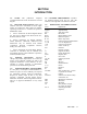
SECTION I INTRODUCTION 1-1. SCOPE. This publication comprises Overhaul Instructions for the IO-520 Series Aircraft Engines. 1-5. CYLINDER ARRANGEMENT. Cylinders are numbered starting from the rear, with odd numbers on the right and even numbers on the left. 1-2. RELATED PUBLICATIONS. Detail part numbers and service assemblies for these engine models are contained in Parts Catalog X-30040A. Operating instructions are contained in Operator's Handbook X-30041. 1-6. a.
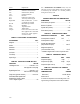
Term . Explanation N.C. N.F. O.D. Press. p.s.i. Rear Right Side National Coarse (thread) National Fine (thread) Outside Diameter Pressure Pounds per square inch Accessory end of engine Side on which Nos. 1, 3 and 5 cylinders are located Revolution per minute Standard Top dead center Temperature Force x lever arm (125 ft.-lbs. force applied one ft. from bolt center or 62-1/2 lbs. applied 2 ft. from center) R.P.M. Std. T.D.C. Temp. Torque TABLE I. PURCHASED ACCESSORIES ACCESSORY QTY Magneto ...........
1-8. OIL SUPPLY AND MEASUREMENT. 1-10. OIL CONSUMPTION. 1-9. The capacity of the oil sump is 12 U.S. quarts. The oil filler cap is attached over the oil filler neck on top of the left crankcase. The oil sump is equipped with an oil level gauge notched and stamped with numerals representing quarts. 1-11. When operated on a rigid test stand at cruise power settings and operating within specified limits oil consumption shall not exceed 1 quart per hour and one –half. FIGURE 1-1.
FIGURE 1-3. THREE-QUARTER RIGHT FRONT VIEW OF THE IO-520-B. (PERMOLD CRANKCASE) FIGURE 1-4. THREE-QUARTER LEFT REAR VIEW OF THE IO-520-B.
FIGURE 1-5. THREE-QUARTER RIGHT FRONT VIEW OF THE IO-520-C. (PERMOLD CASE) FIGURE 1-6. THREE-QUARTER LEFT REAR VIEW OF THE IO-520-C.
FIGURE 1-7. THREE-QUARTER RIGHT FRONT VIEW OF THE IO-520-D. (SANDCAST CRANKCASE) FIGURE 1-8. THREE-QUARTER LEFT REAR VIEW OF THE IO-520-D.
FIGURE 1-9. THREE-QUARTER RIGHT FRONT VIEW OF THE IO-520-J. (SANDCAST CRANKCASE) FIGURE 1-10. THREE-QUARTER RIGHT FRONT VIEW OF THE IO-520-L.
FIGURE 1-11. INSTALLATION DRAWING FOR THE IO-520-A,D,E,J,K & L. FIGURE 1-12. INSTALLATION DRAWING FOR THE IO-520-B.
FIGURE 1-13. INSTALLATION DRAWING FOR THE IO-520-C.
Intentionally Left Blank
SECTION II GENERAL DESCRIPTION 2-1. SIGNIFICANT DIFFERENCES. Specific detail parts differences in the IO-520 Series will be noted in the Parts Catalog. Significant configuration differences in the IO-520 Series are primarily related to the two different crankcases. The SAND CAST CRANKCASE has provision for a belt driven generator (or alternator) located at the accessory end of the engine. The oil cooler is in front of the number 5 cylinder and an integral type oil screen is incorporated in the oil pump.
base flanges. The governor mount pad is located at the lower front corner. On the right permold crankcase an alternator pad is located at the front. c. The crankcase interior is ventilated by a breather consisting of a tube and baffles assembly with a side extension for hose attachment. The breather assembly is pressed into the upper left crankcase. 2-4. CRANKSHAFT. The six throw, steel alloy forging is machined allover except for some portions of the crankcheeks.
sockets and rocker faces and pressed-in bronze bearings. They are drilled -for lubrication. Pushrods are constructed of steel tubes and pressedin, hardened, forged steel ball ends, which are center drilled for oil passages. The pushrod housings are beaded steel tubes. The bead at the cylinder end retains a packing ring between two washers. The bead at the crankcase end retains a heavy spring, washer, packing ring and second washer. 2-10. FUNCTIONAL SYSTEMS. 2-11.
FIGURE 2-2. GEAR TRAIN DIAGRAM (TYPICAL WITH SANDCAST CRANKCASE). 1. 2. 3. 4. 5. 6. 7. 8. 9. 10. 11. 12. 13. 14. 15. 16. 17. 18. 19. 20. 21. 22. 23. 2-4 Crankshaft gear......................................................... Crankshaft................................................................. Camshaft cluster gear............................................... Camshaft................................................................... Hydraulic tappet .............................................
FIGURE 2-3. GEAR TRAIN DIAGRAM (TYPICAL WITH PERMOLD CRANKCASE). 1. 2. 3. 4. 5. 6. 7. 8. 9. 10. 11. 12. 13. 14. 15. 16. 17. 18. 19. 20. 21. 22. 23. Crankshaft gear......................................................... Crankshaft................................................................. Camshaft gear........................................................... Camshaft................................................................... Hydraulic tappet ................................................
FIGURE 2-4. LUBRICATION SYSTEM (TYPICAL WITH SANDCAST CRANKCASE).
FIGURE 2-5. LUBRICATION SYSTEM (TYPICAL WITH PERMOLD CRANKCASE).
d. Passageways from the left crankcase gallery direct oil to the front, intermediate and rear main bearings. e. Four drilled passages radiating from the rear main bearing conduct lubricating oil to the adapter ports of the fuel pump drive, right and left magneto and accessory drives and to starter shaftgear bearing. An intersecting passage directs oil to the idler gear support. f. Oil is returned to the sump through a system of oil transfer tubes and drain holes. 2-14.
2-16. The barrel type hydraulic lifter (See Figure 26) consists of a steel body (1), an expanding spring (2), and a check valve assembly (3, 4 and 5), a plunger (6), a socket (7) for pushrod end, and a retaining ring (8). A groove (9), around outside of body picks up oil from crankcase supply hole only when lifter is near outer end of its stroke so engine pressure will not "pump up" plunger and hold the valve off its seat.
Intentionally Left Blank
SECTION III SPECIAL TOOLS AND EQUIPMENT 3-1. It is advisable to have an engine transportation stand (Figure 3-4) on which the engine can be inverted so certain parts can be removed or installed easily. 3-2. The tool in Figure 3-1 is used for installing the needle bearing in the starter adapter. This tool can be manufactured locally in accordance with the dimensions specified. 3-3. For replacing an outer sleeve on the ignition harness, use a Thomas and Betts Crimping Tool, No. WT-217. 3-4.
FIGURE 3-4. ENGINE TRANSPORTATION STAND FIGURE 3-5. VALVE SPRING COMPRESSOR, BORROUGHS NO. 5202 BORROUGHS NO. 5204 RIGHT HAND BORROUGHS NO. 5203 LEFT HAND FIGURE 3-6.
SECTION IV DISASSEMBLY 4-1. GENERAL. . 4-2. AIRCRAFT PARTS AND ACCESSORIES. 4-3. Instructions in this section are based on the assumption that all parts attached by the aircraft manufacturer, except optional pumps, have been removed. 4-4. Accessories supplied by the engine manufacturer may be serviced according to instructions supplied by the applicable accessory manufacturer. 4-5. EXTENT OF DISASSEMBLY.
FIGURE 4-1. FUEL INJECTION SYSTEM (IO-520-A,E,F,J,K & L) 1. Clamp, Fuel Discharge Tube 2. Tube Assembly 3. Nozzle Assembly 4. Nozzle 5. Shield, Dust 6. Screen 7. Jet 8. Hose Assembly 9. Hose Assembly 10. Hose Assembly 11. Nut, Plain, Hex 12. Washer, Lock 13. Washer, Plain 14. Shroud Assembly 15. Pin, Cotter 16. Washer, Plain 17. Washer, Wave 18. Spring, Throttle 19. Nut, Elastic Stop 20. Rod End, Special 4-2 21. Spring, Compression 22. Rod and Link Assembly 23. Screw, Special 24. Washer, Tab 25.
FIGURE 4-2. FUEL INJECTION SYSTEM (IO-520-B) 1. Clamp 2. Tube Assembly 3. Nozzle Assembly 4. Jet 5. Screen 6. Shield, Dust 7. Nozzle 8. Hose Assembly 9. Hose Assembly 10. Clamp 11. Clamp 12. Bracket 13. Nut, Plain, Hex 14. Washer, Lock 15. Washer, Plain 16. Bolt 17. Bolt 18. Washer, Plain 19. Pin, Cotter 20. Washer, Plain 21. Washer, Wave 22. Nut, Elastic Stop 23. Rod End, Special 24. Spring, Compression 25. Rod and Link Assembly 26. Nut, Plain, Hex 27. Washer, Lock 28. Washer, Plain 29. Screw 30.
FIGURE 4-3. FUEL INJECTION SYSTEM (IO-520-C) 1. Tube Assembly 2. Clamp 3. Nozzle Assembly 4. Nozzle 5. Shield, Dust 6. Screen 7. Jet 8. Hose Assembly 9. Hose Assembly 10. Nut 11. Washer, Lock 12. Washer, Plain 13. Screw, Cap 14. Washer, Tab 15. Shroud Assembly 16. Pin, Cotter 17. Washer, Plain 18. Pin, Cotter 19. Washer, Plain 4-4 20. Washer, Wave 21. Washer, Wave 22. Rod and Link Assy. 23. Nut, Elastic Stop 24. Rod, End, Special 25. Spring, Compression 26. Screw, Special 27. Washer, Tab 28.
FIGURE 4-4. FUEL INJECTION SYSTEM (IO-520-D) 1. Tube Assembly 2. Clamp 3. Nozzle Assembly 4. Nozzle 5. Shield, Dust 6. Screen 7. Jet 8. Hose Assembly 9. Hose Assembly 10. Hose Assembly 11. Body Assembly 12. Pin, Cotter 13. Pin, Cotter 14. Washer, Wave 15. Rod and Link Assy. 16. Nut, Elastic Stop 17. Rod, End, Special 18. Spring, Compression 19. Nut, Plain, Hex 20. Washer, Lock 21. Washer, Plain 22. Shroud 23. Bolt, Special 24. Washer, Tab 25. Control Assembly 26. Pin 27. Lever 28. Washer, Wave 29.
4-11. FUEL INJECTION SYSTEM (See Figures 4-1, 4-2 and 4-3). 4-12. MAGNETO AND ACCESSORY DRIVES (See Figure 4-5). a. Use the following basic procedure to disassemble the fuel injection system on the IO-520 Series. a. Remove two sets of attaching parts (1, 2, 3) and six sets of attaching parts (4, 5,6) and remove adapter assembly (7) and related parts as a unit. b. Remove gear assembly (18), magneto drive coupling bushings (21) and retainer (22). c.
4-13. INDUCTION SYSTEM. a. IO-520-A, B, C, F,J, K, L (See Figure 4-6). (1.) Loosen hose clamps (1) or clamp assemblies (2) on hoses (3) or (4) and remove elbows (5, 6) or elbow assembly (7). (2.) Remove attaching parts (8, 9) loosen hose clamps (II, 12) and remove balance tube (13) and bracket (10). (3.) Loosen hose clamps (14) from hoses (15) and remove attaching parts (16, 17, 18). Remove intake manifold tubes (19,20) and gasket (21). (4.) BRACKETS.
FIGURE 4-6. INDUCTION SYSTEM. (A,B,C,F,J,K & L) 1. Clamp, Hose 2. Clamp Assembly 3. Hose, Intake Manifold 4. Hose 5. Tube Assy., Elbow, 2-4-6 Side 6. Tube Assy., Elbow, 1-3-5 Side 7. Manifold Assembly 8. Bolt 9. Washer, Lock 10. Bracket 11. Clamp 12. Clamp 13. Tube Assembly, Balance 14. Clamp, Hose 15. Hose 16. Screw 17. Washer, Lock 18. Washer, Plain 19. Tube Assembly 4-8 20. Tube Assembly 21. Gasket 22. Plug, Pipe 23. Screw 24. Washer, Lock 25. Nut, Plain, Hex 26. Washer, Lock 27. Screw 28.
FIGURE 4-7 INDUCTION SYSTEM. (IO-520-D) 1. Clamp 2. Hose 3. Tube 4. Tube 5. Screw 6. Washer, Lock 7. Bracket 8. Clamp 9. Clamp Assembly 10. Tube Assembly 11. Clamp, Hose 12. Screw 13. Washer, Lock 14. Washer, Plain 15. Tube Assembly 16. Tube Assembly 17. Gasket 18. Plug, Pipe 19. Throttle Assy.
FIGURE 4-8 INDUCTION SYSTEM. (IO-520-E) 1. Clamp 2. Hose 3. Tube Assembly 4. Tube Assembly 5. Bolt 6. Washer, Tab 7. Bracket 8. Clamp 9. Clamp Assembly 10. Tube Assembly 11. Clamp 12. Screw 13. Washer, Lock 4-10 14. Washer, Plain 15. Tube Assembly 16. Tube Assembly 17. Gasket 18. Nut, Hex 19. Washer, Lock 20. Nut 21. Washer, Lock 22. Screw 23. Nut 24. Washer, Lock 25. Bracket 26. Grommet 27. Sleeve 28. Throttle Assembly 29. Nut. Self-Locking 30. Bolt 31. Nut, Plain, Hex 32. Washer, Lock 33. Bracket 34.
FIGURE 4-9 OIL SUMP (STAMPED ALUMINUM SHEET METAL IO-520-A,C,D,E,F & K) 1. Plug, Oil Drain 2. Gasket, Annular 3. Screw 4. Washer, Lock 5. Washer, Plain 6. Sump Assembly, Oil 7. Gasket, Oil sump 8. Screw 9. Screw 10. Washer, Plain 11. Tube Assembly 12. Gasket 13. Bolt. 14. Washer, Special 15. Nut 16. Gasket, Annular 17.
FIGURE 4-10 OIL SUMP (CAST ALUMINUM IO-520-B) 1. Plug, Oil Drain 2. Gasket 3. Nut, Plain, Hex 4. Washer, Lock 5. Washer Plain 6. Bracket, Engine Mount 4-12 7. Screw 8. Washer, Lock 9. Washer, Plain 10. Sump, Oil 11. Felt 12. Gasket, Oil Sump 13. Screw 14. Nut 15. Gasket, Annular 16. Tube Assembly 17.
1. 2. 3. 4. 5. 6. 7. 8. 9. 10. 11. Screw Washer, Lock Washer, Plain Cooler Assembly Gasket Nut, Plain, Hex Washer, Lock Washer, Plain Plate Plug, pipe Gasket 1. 2. 3. 4. 5. 6. 7. 8. 9. 10. 11. 12. 13. 14. 15. Washer, Plain Washer, Lock Nut, Plain, Hex Washer, Plain Washer, Lock Nut, Plain, Hex Oil Cooler Baffle Gasket “O” Ring Gasket Valve Assembly Plug Plug Support Assembly FIGURE 4-11 OIL COOLER (TYPICAL ON SANDCAST CRANKCASE). FIGURE 4-12 OIL COOLER (TYPICAL ON PERMOLD CRANKCASE).
d. Remove nut (13) and washer (14), and bolts (15, 16); Idler kiss bracket (17) will come off at this time. Generator (18) should pull free. Remove special washers (19), bushings (20), and bushing spacer (21). Remove support bracket (22) and mounting bracket (23) by removing nuts and washers retaining them to the crankcase. c. Remove bracket adjusting screw (4) and washer (5). Remove bracket retaining screw and bracket (6). 4 d. Remove nut (9) and bolts (10, 12).
1. Belt 2. Spacer 3. Sheave 4. Bolt 5. Washer, Plain 6. Bracket Assembly 7. Nut, Elastic Stop 8. Pin, Idler Kiss 9. Nut, Plain, Hex 10. Bolt 11. Washer, Plain 12. Bolt 13. Washer, Plain 14. Generator 15. Washer, Special 16. Bushing 17. Spacer, Bushing 18. Bolt 19. Bracket Assembly 20. Bracket FIGURE 4-14. GENERATOR ASSEMBLY (IO-520-E) 1. Bolt 2. Washer, Plain 3. Alternator 4. Support Assembly, Baffle 5. Pin, Cotter 6. Nut, Slotted, Hex 7. Woodruff Key 8. Washer, Thrust 9. Gear 10. Bushing 11.
4-21. STARTER AND STARTER DRIVE ADAPTER (See Figure 4-16). 4-22. STARTER AND STARTER ADAPTER (See Figure 4-17). a. Remove two sets of attaching parts (1, 2, 3) and pull starter from starter adapter studs. Remove "O" ring (5). a. Remove attaching parts ( 1, 2) and pull 4 starter (3) from adapter studs. Remove “O” ring (4). b. Remove attaching parts (6 through 11) and pull starter adapter assembly from crankcase studs. Remove gasket (12). c.
FIGURE 4-16. STARTER ADAPTER WITH GENERATOR DRIVE SHEAVE. (SANDCAST CRANKCASE) 1. Nut 2. Lockwasher 3. Washer, Plain 4. Starter 5. “O” ring 6. Nut 7. Washer, Lock 8. Washer, Plain 9. Bolt 10. Bolt 11. Washer, Lock 12. Gasket 13. Nut 14. Washer, Lock 15. Washer, Plain 16. Sheave 17. Screw 18. Washer, Lock 19. Washer, Plain 20. Indicator, Timing 21. Woodruff Key 22. Cover 23. Gasket 24. Sleeve 25. Oil Seal 26. Retaining Ring 27. Screw 28. Tab Washer 29. Clutch Spring 30. Bearing, Ball 31. "0" Ring 32.
FIGURE 4-16. STARTER ADAPTER WITH GENERATOR DRIVE SHEAVE. (SANDCAST CRANKCASE) 1. Nut, Plain, Hex 2. Washer, Plain 3. Motor, 24 Volt, Starter 4. “O” ring 5. Nut, Plain, Hex 6. Washer, Lock 7. Washer, Plain 8. Gasket 9. Nut, Plain, Hex 10. Washer, Lock 4-18 11. Washer, Plain 12. Cover, Starter Adapter 13. “O” ring 14. Ring, Retaining 15. Bearing, Ball 16. Screw 17. Washer Tab 18. Spring,' Clutch 19. Gear, Starter Worm 20. Bearing, Needle 21. Shaftgear Assembly, Starter 22. Ring, Retaining 23.
4-23. OIL PUMP ASSEMBLY (See Figure 4-18). a. Loosen oil screen (6) and tachometer drive housing (12) to facilitate later removal. (Tachometer drive housing has a left hand thread.) Remove ten sets of attaching parts (1, 2, 3) and pull pump assembly to the rear. Remove gasket (5). b. Remove oil screen (6) and gasket (7). c. Remove attaching parts (8,9,10) and separate cover (11) from pump housing (4). Remove tachometer drive housing (12). Press oil seal (15) from housing.
i. Remove hydraulic valve lifter assemblies (43). It is recommended that all hydraulic lifters be replaced at each major overhaul regardless of condition. If for any reason lifters are removed for inspection before the overhaul period is reached, they must be placed back in the same location from which they were removed. 4-26. SANDCAST CRANKCASE (See Figure 421). a. Oil gauge rod and guide and brackets (items 1 through 11) are shipped loose with the engine, and were probably returned in the same manner.
NOTE Do not attempt to remove bolt and washer adjacent to right magneto upper stud. These two parts are installed be- fore the stud and cannot be removed before removal of that stud without damage to crankcase hole. Take care to avoid damage to bolt threads during subsequent overhaul operations. h. Lift off right crankcase. Lift out camshaft assembly and governor driven gear (See Figure 4- 23).
FIGURE 4-18. OIL PUMP (INTEGRAL TYPE OIL SCREEN). 1. Nut 2. Washer, Lock 3. Washer, Plain 4. Housing 5. Gasket 6. Screen Assembly 7. Gasket 8. Nut 9. Washer, Lock 10. Washer, Plain 11. Cover 12. Housing 13. Gasket 14. Shaftgear 15. Seal, Oil 16. Nut 17. Washer, Lock 4-22 18. Washer, Plain 19. Cover 20. Nut 21. Washer, Lock 22. Washer, Plain 23. Cover 24. Gasket 25. Seal, Oil 26. Gear Assembly 27. Screw 28. Washer, Lock 29. Washer, Plain 30. Cover 31. Gasket 32. Stud 33. Gear 34. Shaftgear 35. Dowel 36.
FIGURE 4-19. OIL PUMP (PERMOLD ENGINE FULL FLOW TYPE FILTER). 1. Filter 2. Nut 3. Lockwasher 4. Washer, Plain 5. Adapter 6. Gasket 7. Nut 8. Lockwasher 9. Washer, Plain 10. Housing, Oil Pump 11. Gasket 12. Nut 13. Lockwasher 14. Washer, Plain 15. Cover 16. Nut 17. Lockwasher 18. Washer, Plain 19. Cover 20. Gasket 21. Screw 22. Lockwasher 23. Washer, Plain 24. Cover 25. Gasket 26. Oil Seal 27. Shaftgear 28. Stud 29. Stud 30. Nut 31. Lockwasher 32. Washer, Plain 33. Cover 34. Gasket 35. Oil Seal 36.
FIGURE 4-20. CYLINDER. 1. Screw, Fillister Head 2. Washer, Lock 3. Washer, Plain 4. Cover, Valve Rocker 5. Gasket 6. Screw 7. Washer, Plain 8. Shaft, Valve Rocker 9. Screw, Drive 10. Bushing 11. Rocker, Valve 12. Washer, Thrust 13. Push .Rod Assembly 14. Housing 15. Spring 4-24 16. Washer 17. Packing 18. Nut, Flanged 19. Nut, Flanged 20. Pin and Plug Assembly 21. Piston 22. Ring, Compression 23. Ring, Compression 24. Ring, Oil Control 25. Ring, Scraper 26. Packing 27. Key, Retainer 28.
FIGURE 4-21. SANDCAST CRANKCASE ASSEMBLY COMPLETE. 1. Rod Assembly, Oil Gauge 2. “O” ring 3. Nut, No. 10-32 4. Washer, Lock 5. Washer, Plain 6. Screw 7. Bracket 8. Clamp 9. Clamp, Hose, Worm Type 10. Housing 11. Hose 12. Cap Assembly, Oil Filter 13. Gasket 14. Screw 15. Neck Assembly, Oil Filler 16. Gasket 17. Nut, Plain, Hex 18. Washer, Lock 19. Washer, Plain 20. Bolt 21. Eye, Engine Lifting 22. Spacer 23. Valve Assembly 24. Bolt 25. Washer, Lock 26. Washer, Plain 27. Nut, Plain, Hex 28. Washer, Plain 29.
FIGURE 4-22. PERMOLD CRANKCASE ASSEMBLY COMPLETE. 1. Gauge and Cap Assy., Oil 2. Screw 3. Washer, Lock 4. Washer, Plain 5. Tube, Oil Filler Assy. 6. Gasket 7. “O” ring 8. Nut, Plain, Hex 9. Washer, Lock 10. Washer, Plain 11. Bolt 12. Eye, Engine Lifting 13. Spacer 14. Nut, Plain, Hex 15. Washer, Lock 16. Washer, Plain 17. Spacer, Gov. Pad 18. Cover, Gov. Pad 19. Gasket 20. Nut, Plain, Hex 21. Washer, Lock 22. Washer, Plain 23. Cover, Camshaft Hole 24. Gasket 25. Nut, Plain, Hex 26. Washer, Plain 4-26 27.
FIGURE 4-23. CAMSHAFT ASSEMBLY 1. Gear, Bevel, Driven 2. Gear, Bevel, Drive 3. Woodruff Key 4. Screw 5. Cam Gear 6. Gear, Camshaft 7. Plug, Pipe 8. Plug, Expansion 9.
FIGURE 4-24. CRANKSHAFT GROUP (TYPICAL OF SANDCAST MODELS 1. Washer, Thrust 2. Bearing, Crankshaft, Main 3. Gear, Idler 4. Bushing, Idler Gear 5. Pin, Cotter 6. Nut, Slotted 7. Bolt, Special 8. Cap 9. Rod, Connecting 10. Bearing 11. Bushing 12. Ring, Retaining 13. Plate, Counterweight 14. Pin, Counterweight 15. Pin, Counterweight 16. Pin, Counterweight 17. Counterweight, Crankshaft 18. Bushing, Counterweight 4-28 19. Nut, Marsden 20. Collar, 1-3-5 Side 21. Collar, 2-4-6 Side 22. Sleeve, Oil Transfer 23.
FIGURE 4-25. CRANKSHAFT GROUP (TYPICAL OF PERMOLD CRANKCASE). 1. Washer, Thrust 2. Bearing, Crankshaft, Main 3. Gear, Idler 4. Pin, Cotter 5. Nut, Slotted, Special 6. Bolt 7. Cap 8. Connecting Rod Assembly 9. Bearing 10. Bushing 11. Ring, Retaining 12. Plate, Counterweight 13. Pin, Counterweight, 6th Order 14. Pin, Counterweight, 4th Order 15. Pin, Counterweight, 5th Order 16. Counterweight Assembly 17. Bushing 18. Nut, Marsden 19. Collar, 1-3-5 Side 20. Collar, 2-4-6 Side 21. "0" Ring 22. Dowel 23.
Intentionally Left Blank
SECTION V CLEANING, REPAIR AND REPLACEMENT 5-1. MATERIALS AND PROCESSES. 5-2. Equipment, materials and processes in general use in aircraft engine overhaul shops are satisfactory for cleaning IO-520 engine parts. 5-3. Aluminum alloy parts can be degreased by spraying with any fortified mineral spirit solvent or by brush application of the same liquid.
since the corner radii at the bottoms of the grooves must not be altered, nor any metal removed from the sides. Discoloration and light scoring need not be removed from piston skirts. The use of abrasive cloth on the skirts is not recommended, because the diameters and cam-ground contour must not be altered. Heavily scored or burned pistons should be discarded. 5-9. VALVES.
TABLE VII. STANDARD AND OVERSIZE STUD IDENTIFICATION torn, install the next larger oversize stud. If the old stud was of the maximum oversize, of if the thread is damaged, the hole may be tapped and a helical coil insert installed for a standard-size stud. Coat the new stud's coarse thread with Alcoa thread lube if the hole is blind or with National Oil Seal compound if the hole goes through to a cavity subject to oil spray. It is advisable to drive the new stud with a tee handle stud driver.
oil with two parts kerosene to prevent over heating of the metal and tearing of the thread. 5-21. To remove a damaged helical coil insert use the proper size of extracting tool for the nominal thread size. Tap it into the insert so that the sharp edges get a good "bite"; then turn the tool to the left, and back out the helical coil until it is free.
FIGURE 5-1.
FIGURE 5-2. INSTALLING TYPICAL HELICAL INSERT FIGURE 5-3. REMOVING SPARK PLUG HOLE HELICAL INSERT. FIGURE 5-4. INSTALLING SPARK PLUG HOLE HELICAL INSERT. FIGURE 5-5. EXPANDING SPARK PLUG HOLE HELICAL INSERT. 5-6 FIGURE 5-6.
seized by score marks, the entire assembly must be replaced. Remove spring by turning as if to unwind it while pulling outward. Be careful not to stretch spring out of shape. Remove check valve housing from plunger with a small screwdriver by prying against plunger shoulder. Do not flip off housing. After housing is loosened lift off, and remove plate (4) and spring (6). 5-28. CONNECTING RODS. CAUTION 1. 2. 3. 4. 5. 6. 7.
FIGURE 5-8. CONNECTING ROD AND BUSHING DIMENSIONS. 5-31. Hardened steel bushings in the crankshaft blades may be removed and replaced if excessively worn. It may be necessary to chill the old bushings to free them. New bushings must be chilled before installation with a suitable drift, and the holes must be smooth. No finishing operation is required for the new bushings, since they are made to final dimensions. They must be driven in to the same positions as the original parts.
Its flange thrust face must be parallel to the parting surface within 0.002 inch (full indicator reading). CAUTION Before boring a new bushing, plug its oil boles with beeswax to exclude cbips from tbe adapter oil groove. Be sure to remove the wax completely after the operation. clean engine lubricating oil. The rear pad of the adapter, rather than the studs, should be supported on a parallel block and a flat block should be used to exert pressure, unless the arbor has a perfect end.
5-36. STARTER DRIVE ADAPTER. The clutch spring sleeve is shrunk and doweled in the housing. If it is necessary to remove the needle bearing in the adapter, a removing driver may be made similar to the driver illustrated in Figure 3-1. Check oil feed holes to the starter adapter shaft- gear. Hole diameter should be .0918-.0968 to reduce possibility of clogging and causing lubrication loss to starter adapter clutch spring.
FIGURE 5-11. EXPLODED VIEW OF IGNITION SYSTEM. 1. High Tension Cable Outlet Plate 2. Outlet Plate Grommet 3. Cable Assy. to No.1 Lower Spark Plug 4. Cable Assy. to No.6 Upper Spark Plug 5. Cable Assy. to No.3 Lower Spark Plug 6. Cable Assy. to No.2 Upper Spark Plug 7. Cable Assy. to No.5 Lower Spark Plug 8. Cable Assy. to No.4 Upper Spark Plug 9. Cable Assy. to No.1 Upper Spark Plug 10. Cable Assy. to No.6 Lower Spark Plug 11. Cable Assy. to No.3 Upper Spark Plug 12. Cable Assy. to No.2 Lower Spark Plug 13.
Intentionally Left Blank
SECTION VI INSPECTION 6-1. DEFINITIONS OF TERMS. 6-2. The following definitions apply to terms used to describe kinds of damage for which parts should be inspected. A. ABRASION: Scratching of a surface, either by motion while in contact with another part or by mechanical cleaning or resurfacing with abrasive cloth or lapping compound. B. BURNING: As applied to valve heads, this term indicates roughening or erosion due to high temperature gases escaping past valve faces.
areas. Inspect all studs for possible bending, looseness or partial removal. Inspect all threaded parts for nicks and other damage to the screw threads. After visual inspection the engine parts should be in three groups: Apparently serviceable parts, repairable parts and parts to be discarded. 6-5. MAGNETIC PARTICLE INSPECTION. Inspection by the Magnaflux method must be conducted on all ferrous parts listed in Table XI, and in accordance with the methods and data in the table before dimensional inspection.
PART NAME Camshaft Journal Diameter (4) Permold Crankcase Journal Diameter (4) Sandcast Crankcase NEW DIMENSION (INCHES) 0.9980 - 0.9990 1.2480 - 1.2490 Hydraulic Valve Tappets Outside Diameter 0.9990 - 0.9995 Crankcase Camshaft Bearings Dia. Permold Crankcase Camshaft Bearings Dia. Sandcast Crankcase Crankshaft Bearing Bore in Crankcase Std. Crankshaft Bearing Bore in Crankcase "B" Configuration. Rear and Intermediate Bearings Only. Tappet Guides Dia. Governor Driven Gear Bearing Dia.
6-6. FLUORESCENT PARTICLE INSPECTION. This process, commonly known under the trade name of "Zyglo", is recommended for inspecting aluminum alloy parts for invisible cracks. The standard operating technique for the process is applicable. 6-7. DIMENSIONAL INSPECTION. 6-8. INSTRUMENTS.
NOTE... If "Alodine" does not adhere to metal a more severe cleaning method must be used. A solution of 12 to 16 ounces of Oakite No. 61, or equal per one gallon of water is preferred. Apply and remove the solution with caution because an alkaline cleaner of this type will remove any "Alodine" film previously applied. Remove cleaning solution thoroughly with plenty of hot water and vigorous brushing.
c. Replacement bushings are available in standard, .0015", .003" and .005" oversize on the outside diameter. d. A special tool for removing and replacing these bushings has been developed by Borroughs Tool and Equipment Corporation, 2429 North Burdick Street, Kalamazoo, Michigan. We recommend that this tool only be used for these operations. e. Counterweight pins are identified by dash numbers stamped on one end.
FIGURE 6-1. INSPECTING RING SIDE CLEARANCE. cam-ground contour should not be altered.
fully, either it is excessively worn or check valve is leaking. To check for leaking valve, repeat compression test while plugging end of oil inlet tube with other hand. If plunger still does not kick back promptly it and the cylinder are excessively worn. If it does kick back on the second test, either check valve seat is worn and leaking or it is dirty. Clean cylinder again and repeat first test (tube open). If plunger still does not kick back, valve is defective.
SUBASSEMBLY AND PART INSPECT NATURE OF INSPECTION SPECIAL CONSIDERATIONS If seats cannot be made serviceable by grinding within width limit, replace seat. Valve Seats Roughness caused by honing. Cooling Fins Cracks and broken areas. Cracked and/or broken cylinder head fins may be re- paired, providing a total of not more than five square inches is, or has been removed. Base Flange If attaching nuts were found loose at disassembly, test for flatness of mounting face. Allow not over 0.
SUBASSEMBLY AND PART CONNECTING ROD ASSEMBLY Bushing SPECIAL CONSIDERATIONS New bushings must be reamed within diameter limits for new parts. Sharp edges must be broken slightly. (Refer to Table of Limits, for wear limit, for new bushing limits and new bushing alignment limits). Diameters, scoring, burning Must be polished before magnetic inspection. Crankpins Diameters, scoring, burning Must be polished before magnetic inspection.
SUBASSEMBLY AND PART Gear INSPECT NATURE OF INSPECTION SPECIAL CONSIDERATIONS Teeth Scoring, burning, pitting, wear enough to alter profile. Valve Lifter Guides Diameter, scoring. Bearing Seats Roughness, wear in tang notches. Refer to Table of Limits. Camshaft Bearings Diameter, scoring, fit of rear bearing between camshaft flanges. See paragraph 6-16. Oil Passages Inspect visually, galleries, main and camshaft bearing supply holes, using inspector’s flashlight to illuminate.
SUBASSEMBLY AND PART Plugs NATURE OF INSPECTION SPECIAL CONSIDERATIONS Threads Look for distortion. Wrench Flats Look for damaged corners. Bore Inside diameter, scoring. Sandcast crankcase only. Seat Roughness. Sandcast crankcase only. Headers, Fins Core Inspect visually for dents, deformed fins, punctures, stripped plug hole threads, cracks and scratches. Machined Surfaces Warpage and scratches. All areas Cracks Seat Roughness Tapped Holes Damaged threads, cracks around holes.
SUBASSEMBLY AND PART Gears INSPECT NATURE OF INSPECTION SPECIAL CONSIDERATIONS Refer to Table of Limits. Shafts Measure diameters and compare with bushing diameters. Gear Teeth Scoring, burning or wear enough to alter tooth profile. Splines Look for wear on side of splines and residual sludge. Gear Bushings Bore Diameters Use telescoping gauge and micrometer caliper. Oil Pressure Relief Valve Plunger Outside Surface Measure diameter. Look for scoring, nicks, etc. Conical Face Roughness.
SUBASSEMBLY AND PART Gears INSPECT NATURE OF INSPECTION Shafts Measure diameters and compare with bushing diameters Gear Teeth Scoring, burning or wear enough to alter tooth profile. Ball Bearing Balls, Cage Surface roughness, out-ofround, excessive depth and looseness Adapter Cover All Areas Cracks, scratches on machined surfaces, damaged mounting holes. Shaft Bearing Look for scoring. Bore Measure Diameter. Oil Seal See that old seal was removed without damage to casting.
SUBASSEMBLY AND PART Fuel Pump Drive Gear INSPECT NATURE OF INSPECTION Teeth Look for chipped, cracked and broken teeth, scoring, burning and wear enough to alter tooth profile. Shaft Measure outside diameter and compare with bore diameter. Gear Plug Make sure that new plug was installed after magnetic particle inspection of gear and visual inspection for cleanliness of center bore. Drive Coupling Fit Check for looseness.
SUBASSEMBLY AND PART INSPECT NATURE OF INSPECTION SPECIAL CONSIDERATIONS MAGNETO AND ACCESSORY DRIVE ASSEMBLY Adapter Gear 6-16 Gear Bushing Measure bore diameter. Oil Seal Observe that old seal has been removed without damage to casting bore. Studs Look for stripped and deformed threads. Teeth Scoring, burning or wear enough to alter tooth profile. Shaft Measure diameters and compare with bushing diameter. Refer to Table of Limits. Refer to Table of Limits.
TABLE X CRANKCASE STUD SETTING HEIGHTS LOCATION Cylinder Mount Pads Engine Mount Pads Oil Cooler Mount Pads Governor Mount Pad Magneto Mount Pad Magneto & Accessory Drive Adapter Pad Idler Pin Pad Starter Drive Pad Fuel Pump Pad Oil Pump Pad Generator Bracket Camshaft Cover Pad Crankcase Thru 1-3-5 Side Accessory End Governor Oil Transfer Collar Cylinder Exhaust Flange Oil Pump Housing Oil Pump Cover Magneto Adapter Oil Sump Starter Adapter THREAD SIZE 7/16-14 X 7/16-20 3/8-16 X 3/8-24 3/8-16 X 3/8-24
TABLE XI MAGNETIC PARTICLE INSPECTION FLUORESCENT METHOD PREFFERED, WET CONTINUOUS PROCEDURE REQUIRED *Method of Magnetization AC or DC Amperes Crankshaft Circular and Longitudinal 2000 Journals, fillets, oil holes, thrust flanges, prop flange. Fatigue cracks, heat cracks, flange cracks, from prop strike Connecting Rod Circular and Longitudinal 1500 All areas. Fatigue cracks. Camshaft Circular and Longitudinal 1500 Lobes, Journals drilled hole edges Heat cracks. Fatigue cracks.
TABLE XII TABLE OF LIMITS Ref. No. Chart No. Model 1 2 1 1 All All 3 4 4 5 6 7 8 9 10 11 12 1 1 1 1 1 1 1 1 1 1 1 All All All All All All All All All All All 13 14 15 16 17 18 19 20 21 22 23 1 1 1 1 1 1 1 1 1 1 1 All All All All All All All All All All All Description CYLINDERS Cylinder bore (lower end of barrel) ........................ Diameter: Cylinder bore choke (at 5.75" from open end of barrel). .............................................. Taper: Cylinder bore out-of-round .............
Ref. No. 39 40 41 42 43 ** Chart No. 1 1 1 1 1 Model Description All All All Bushing in connecting rod. .................................... Diameter: Bolt in connecting rod ............................................ Diameter: Connecting rod bearing on crankpin (tri-metal bearing) ............................................ Diameter: Connecting rod on crankpin .........................End Clearance: Connecting bearing and bushing............................................ ....................
Ref. No. 70 70 71 72 73 Chart No. 3 2 3 2 3 Model Description All S P S P Governor drive shaft in crankcase. ........................ Diameter: Idler gear support pin in crankcase (front). ........... Diameter: Idler gear support bushing in crankcase (front) ..... Diameter: Idler gear support pin in crankcase (rear) ............. Diameter: Idler gear support bushing, flanged, in crankcase (rear) ...........................................
Serviceable Limit Ref. No. 99 100 101 102 Chart No. 2/3 2/3 2 3 Model Description All All S P Oil pump driven gear shaft in oil pump housing ........ Diameter: Oil pump driven gear on shaft. .................................. Diameter: Oil pump driven gear in housing. ............................... Diameter: Oil pump driven gear in housing................................ Diameter: -0.0040L 0.0045 L 0.0070L 103 104 2/3 2/3 TACHOMETER DRIVE ASSEMBLY Tachometer drive shaft in oil pump cover. .......
Ref. No. 137 Chart No. 3 Model 138 139 140 141 142 4 4 2 3 3 All All S P P 143 2 S 144 3 P 2 S 2 S 3 P 2 S 3 P 145 146 2 2 All S 147 1 All 1 All 1 All 1 All 148 C Description Tachometer drive gear and tachometer driven gear ........................................................... Backlash: Starter shaftgear and crankshaft gear. ...................... Backlash: Starter worm wheel gear and worm gear. .................
TABLE XIII TABLE OF TIGHTENING TORQUES Ref. No. Chart No. Model Special Applications Thread Size Qty. In. Lbs. Torque Ft. Lbs. T1 3 P Crankcase through bolt 3/8-24 1 370-390 30.8-32.5 T2 2/3 All Crankcase through bolt (nose) 7/16-20 2 490-510 40.8-42.5 T3 2/3 All Crankcase through bolt (dowel type) 1/20 8 T4 3 P Crankshaft face gear screw (alt.) 5/16-24 4 140-150 11.7-12.5 T5 2/3 All Crankshaft gear screw 5/16-24 6 380-420 31.7-35.
TABLE XIV GENERAL USE – TIGHTENING TORQUES BOLTS, NUTS & SCREWS SIZE IN. LBS. DRIVING STUDS FT. LBS. 8-32 17.5-22.5 1.5-1.9 10-32 36.0-50.0 3.0-4.2 ¼-20 75.0-85.0 6.3-7.1 ¼-28 90.0-110.0 7.5-9.1 5/16-18 155-175 13.0-14.6 5/16-24 180-220 15.0-18.4 3/8-16 220-260 18.3-21.7 3/8-24 275-325 22.9-27.1 7/16-14 7/16-20 400-450 33.3-37.5 ½-20 550-600 45.8-50.0 IN. LBS. FT. LBS. 50.0-70.0 4.2-5.8 100-150 8.3-12.5 200-174 16.6-22.8 300-424 25.0-35.
FIGURE 6-2. TABLE OF LIMITS CHART (1 OF4).
FIGURE 6-2. TABLE OF LIMITS CHART (2 OF4).
FIGURE 6-2. TABLE OF LIMITS CHART (3 OF4).
FIGURE 6-2. TABLE OF LIMITS CHART (1 OF4).
Intentionally Left Blank
SECTION VII ASSEMBLY OF SUBASSEMBLIES 7-1. NEW PARTS. Parts which require protection from atmospheric dust and moisture are wrapped or boxed individually or in sets. These should not be unpacked until they are ready to be installed. This is especially true of precision bearing inserts and antifriction bearings. Check other new parts on receipt for damage done in transit.
f. Place cover and tachometer drive assembly on pump housing, turning drive gear to mesh bevel gears, and attach it temporarily with two sets of attaching parts (8,9, 10). NOTE The oil screen and left-hand threaded tachometer drive housing can best be tightened after being installed on the engine. 7-7. OIL PUMP ASSEMBLY -PERMOLD ENGINE FULL FLOW TYPE FILTER (See Figure 4-19). a.
b. Install clutch spring (18) on worm wheel (19). Turn spring so it tends to unwind until offset end drops into gear hub groove. Position spring on gear so screw notch is aligned with screw hole in gear web. Install tab washer (17) and screw (16). c. Lubricate spring, sleeve and shaftgear liberally with clean oil. Press worm wheel, bearing (20) and spring assembly onto shaftgear (21). Install bearing (15) and retaining ring (14) on shaftgear. Insert shaftgear and worm wheel assembly into adapter.
7-13. CRANKSHAFT AND CONNECTING RODS -TYPICAL OF SANDCAST CRANKCASE (See Figure 4-24). a. Lay crankshaft on a bench with a notched wood block under front and rear journals. b. Layout connecting rods, caps, bolts and nuts (9, 8, 7, 6) opposite crankpins according to position number stamped on bolt bosses. Install new bearing insert in each rod and cap so their ends project the same distance. c.
7-15. CAMSHAFT (See Figure 4-23). a. Tap a Woodruff key (3) on front end of camshaft (9) and install bevel gear (2). b. Install gears (5 and 6) on the IO-520-A camshaft and gear (6) only on the IO-520-B and C camshafts, and secure with four screws (4). WARNING Camshaft (permold engines) must have rear pipe plug (7) and front expansion plug (8) installed in camshaft before camshaft is assembled in engine. 7-16. CRANKCASE, SANDCAST (See Figure 421). a.
FIGURE 7-3.
FIGURE 7-4.
FIGURE 7-5.
SECTION VIII FINAL ASSEMBLY AND TEST 8-1. GENERAL INSTRUCTIONS. 8-2. LUBRICATION. Apply clean engine lubricating oil liberally to all bare steel surfaces, journals, bearings and bushings, before and/or after installation, depending on accessibility, except where special lubricants are mentioned. 8-3. TIGHTENING TORQUES. See Table of Tightening Torques, Section VI and instructions in paragraph 7-2. 8-4. CLEARANCES. Wherever possible, measure clearances of running parts as they are installed.
c. Insert governor driven gear (1, Figure 4-23) into its bearing. d. Lay camshaft assembly in its bearings in left crankcase, meshing spur gear teeth with those of crankshaft gear so that timing marks are aligned in the manner illustrated in Figure 8-2, and turning governor driven gear to mesh it with driver gear. FIGURE 8-3. ALIGNMENT OF TIMING MARKS. 1. Crankshaft gear timing marks 2. Camshaft gear timing mark FIGURE 8-2. ALIGNMENT OF TIMING MARKS. e.
q. Attach right crankcase mount brackets to the assembly stand and rotate stand until engine is upright as shown in Figure 8-4. r. Install generator mount bracket (31) and secure with attaching parts (24 through 30). s. Install, but do not tighten support pin attaching parts (58, 59). 8-7. 22). CRANKCASE, PERMOLD (See Figure 4- a. Install mounting legs on the left crankcase of the IO-520-C and attach to assembly stand, supported as shown in Figure 8-1.
j. Insert, from above, through bolts (58, 59,60, 61). Tap all of these through to centered positions with non-marring hammer. These bolts align crank- case castings and bearings. 8-8. CYLINDERS AND PISTONS. k. Install a washer (30) and flanged nut (29) on each of the two front through bolts. Install an "0" ring (47), plain washer (46), lockwasher (45) and nut (44) on extreme upper rear through bolt on right crankcase. b. Place piston over the rod with the position number toward the propeller flange. l.
FIGURE 8-7 TORQUING SEQUENCE a. Nuts on both ends of thru bolts must torqued. b. All stud and thru bolt threads to be lubricated with castor oil. ASSEMBLY PROCEDURE. 1. Insert thru bolts. 9. Repeat above on cylinder No. 1 2. Snug bolts No. 27,28,43,44. 10. Tighten bolts No. 40 thru 57 to specified torque in sequence shown. 3. Install cylinders 4 & 5. Tighten stud nuts to 300450 in. lbs. 4. Tighten thru bolts No. 1,4 & 9 to 300-400 in. lbs. in sequence shown. 5.
FIGURE 8-8 TORQUING SEQUENCE a. Nuts on both ends of thru bolts must torqued. b. All stud and thru bolt threads to be lubricated with castor oil. ASSEMBLY PROCEDURE. 1. Insert thru bolts. 9. Repeat above on cylinder No. 1 2. Snug bolts No. 27,28,54& 56. 10. Tighten bolts No. 38 thru 64 to specified torque in sequence shown. 3. Install cylinders 4 & 5 and Tighten stud nuts to 350 in. lbs. 4. Tighten thru bolts No. 1 & 4 to 350 in. lbs. in sequence shown. 11.
g. As soon as each cylinder has been installed, secure it moderately with flange nuts (18, 19, Figure 4-20). h. Tighten flanged nuts according to sequence in Figure 8-7 or 8-8 or 8-9. i. Install spark plugs and gaskets in upper cylinder holes. 8-9. OIL PUMP-INTEGRAL SCREEN (See Figure 4-18). TYPE OIL a. Remove two sets of attaching parts and remove tachometer drive and pump cover. b. Spread a thin film of No.3 Aviation Permatex on the rear parting surface of the oil pump housing. Lay No.
FIGURE 8-11. INSTALLING PUSHROD HOUSING. 1. 2. 3. 4. 5. 6. FIGURE 8-12. BOTTOM VIEW WITH VALVE MECHANISM AND OIL SUCTION TUBE INSTALLED. SANDCAST CRANKCASE.
b. Lubricate spur gear and mesh it with crankshaft gear as adapter is placed in position. Seat adapter against gasket. Secure adapter to sandcast crankcase with two sets of nuts and washers and two bolts and lockwashers. Attach lower generator support bracket as shown in Figure 8-10. Secure adapter to permold crankcase with five sets of nuts, plain washers and lockwashers. 8-14. GENERATOR (See Figure 4-13). a. Install upper support bracket components (7 through 12) and secure it with bolt (6). FIGURE 8-13.
8-17. OIL COOLER -TYPICAL OF SANDCAST CRANKCASE (See Figure 4-11). a. Install new gasket (11) on crankcase studs. Install oil cooler end plate (9) on crankcase. Secure with five sets of attaching parts (6, 7, 8). b. Install new gasket (5) and oil cooler (4) on oil cooler end plate. Secure with twelve sets of attaching parts (1,2, 3). 8-18. OIL COOLER -TYPICAL ON PERMOLD CRANKCASE (See Figure 4-12). a. Install baffle support assembly (15) on crankcase through bolts. b.
b. Place a hose clamp on each end of cylinder intake tube so it faces center tube. Push end tubes into hose previously installed on center intake tubes. Work hose clamps over ends of hoses, but not past bead. Do not tighten at this time. c. Push a hose on each front and rear intake tube and install a clamp on overlapping portion behind tube bead. Tighten these clamps. d. Lay a new gasket on intake flange of each cylinder.
Position hoses (2) over beads and secure with clamps(1). 8-24. INDUCTION SYSTEM, IO-520-E (See Figure 4-8). a. Push a new hose (2) on either end of center intake tubes. Slide one hose clamp (11) to a point midway on overlapping portion. Turn each clamp so that a screwdriver can be aligned with its screw and yet clear of the stand when tube is installed. Tighten only enough to hold clamp in position. b. Place a hose clamp (11) on each end of cylinder intake tubes so it faces center tube.
8-27. PLACING CRANKSHAFT IN TIMING POSITION TYPICAL OF SANDCAST CRANKCASE. a. Cover the lower spark plug hole with the thumb and turn crankshaft clockwise until pressure is felt on thumb. The timing marks on the crankshaft flange are now turning towards the bottom parting line of the crankcase halves. b. Using an adjustable square or depth gauge on the front of the crankshaft flange, align the applicable timing mark on the crankshaft flange with the crankcase bottom parting line flange. 8-28.
Position bracket so that its centerline is 21-1/4 inches from edge of No. 2R ferrule and 7-1/2 inches from edge of No.6 ferrule. f. Install all spark plugs not already in place with smooth copper gaskets. Tighten all plugs to torque specified in Table of Limits, Section VI. g. Insert cable terminal sleeves into the proper plugs and screw on the elbow coupling nuts only enough to keep the elbows from turning. Keep the lower spark plug cables above the intake manifold and inside the intake elbows. h.
8-32. FINAL PARTS. a. Install gaskets and covers on mount pads behind magneto drive gears and attach with four sets of plain washers, lockwashers and nuts. 8-33. TESTING AFTER OVERHAUL. 8-34. TEST STAND. After each major overhaul, engine performance should be tested and new parts run-in while the engine is mounted on a rigid test stand, preferably enclosed in cell of such design that recirculating air is held to a minimum.
8-41. ELECTRICAL WIRING. A 24-volt storage battery must be connected by a No. 0 stranded copper cable from its positive terminal to the power terminal of the starter or starter solenoid. The battery negative terminal must be connected to the engine or both battery terminal and engine may be grounded. A small insulated wire should connect the starter solenoid coil terminal to a 5 ampere pushbutton switch. The other switch terminal must be connected to the engine or both to common ground.
b. Turn magneto switch to "BOTH" position. maintain 2.5 to 3.0 psi nozzle pressure. DO NOT use boost pump after engine is running smoothly. c. Press boost pump button and hold it until 2.5-3.0 psi nozzle pressure is obtained; then release boost pump button and press starter button. 8-48. PRESERVATION. If the engine is not to be installed in an aircraft and placed in service immediately, an additional period of 15 minutes test time will be required to preserve the engine internally.
TABLE XVII. STANDARD ACCEPTANCE TEST FOR IO-520, 285 H.P. ENGINE PROPELLER STAND Note: Engine oil pressure must be supplied to propeller transfer collar during all testing. Period Time – Minutes RPM 1 5 1200 2 5 1600 3 10 2450 4 15 Rated RPM (adjust engine – fuel flow, pr., ect.,) (Reduce RPM for adjustments). 5 10 Engine Parameter checks (fuel inj., Oil pr., temp. etc., - see applicable data) 2100 mag check (3.(b)). 6 10 2450 7 5 Idle RPM (cooling period - 300° max.
TABLE XVII. STANDARD ACCEPTANCE TEST FOR IO-520, 300 H.P. ENGINE PROPELLER STAND Note: Engine oil pressure must be supplied to propeller transfer collar during all testing. Period Time – Minutes RPM 1 5 1200 2 5 1600 3 10 2450 4 15 Rated RPM (adjust engine – fuel flow, pr., ect.,) (Reduce RPM for adjustments). 5 10 Engine Parameter checks (fuel inj., Oil pr., temp. etc., - see applicable data) 2100 mag check (3.(b)). 6 10 2450 7 5 Idle RPM (cooling period - 300° max.
Intentionally Left Blank
SECTION IX IO-520-M The IO-520-M is similar to the other Permold engines covered in Sections I thru VIII except that the air throttle body is air frame mounted. Those systems which are unique to the IO-52D-M, the Induction System and the Fuel Injection System are covered on the following pages. The instructions contained in Sections I thru VIII pertaining to the Permold engine design, together with the parts catalog, will provide adequate instructions for the overhaul of the IO-520-M engine. 9-1.
b. Remove attaching parts (17,18) Clamp (16) and remove balance tube (16) and bracket (14). c. Remove attaching parts (21 thru 24) and re move bracket (20). Remove clamp (26) and separate riser (12) and flexible coupling (25). 9-2. INSPECTION. a. Inspect intake tubes for distortion, cracks and outof-roundness. b. Inspect stud in riser for straightness and thread damage. Stud height should be 1.04 inches. 9-3. REASSEMBLY. a. Push a new hose (9) on either side of center intake tube (2).
FIGURE 9-2. FUEL INJECTION SYSTEM. 1. Gasket, Fuel Pump to Crankcase 2. Coupling 3. Fuel Pump 4. Washer, Holding 5. Washer, Lock 6. Nut 7. Throttle Assembly 8. Bushing 9. Collar 10. Pin 11. Washer, Wave 12. Washer, Plain 13. Lever Assembly 14. Bushing 15. Shaft, Throttle Plate 16. Plate, Throttle 17. Screw 18. Screw, Adjusting 19. Spring 20. Control Assembly 21. Washer Tab 22. Bolt 23. Lever 24. Rod Assembly 25. Nut 26. Spring 27. Rod End 28. Nut, Self Locking 29. Washer, Wave 30. Washer, Plain 31.
FIGURE 9-3.
FIGURE 9-4.
FIGURE 9-5.
TABLE XIX. TEST OPERATING LIMITS FEATURE IO-520-M Maximum takeoff power Maximum continuous power Full throttle speed (RPM) Idling speed (RPM) Fuel grade (Octane) Fuel consumption at full throttle (Lbs./Hr. Fuel pump pressure at full throttle (psi) Fuel pump pressure at idle (psi) Metered fuel pressure at full throttle (psi) Metered fuel pressure at idle (psi) Engine intake air temperature Engine intake air pressure (Max.) (In. H2O) Manifold pressure at full throttle (In.
TABLE XX. STANDARD ACCEPTANCE TEST PROPELLER STAND Note: Engine oil pressure must be supplied to propeller transfer collar during all testing. Period Time – Minutes RPM 1 5 1200 2 5 1600 3 10 2450 4 15 Rated RPM (adjust engine – fuel flow, pr., ect.,) (Reduce RPM for adjustments). 5 10 Engine Parameter checks (fuel inj., Oil pr., temp. etc., - see applicable data) 2100 mag check (3.(b)). 6 10 2450 7 5 Idle RPM (cooling period - 300° max.
SECTION X IO-520-BB,CB,MB 10-1 INTRODUCTION A. Information contained herein applies to the modified crankshaft version of the Permold IO-520 engines (IO520 BB, CB, MB). Only those instructions which are different from the standard models (IO-520 B, BA, C, M) will be covered. B. For overhaul instructions not contained in these pages, use the instructions contained in sections 1 thru 9 for the standard versions. 10-2 GENERAL A.
TABLE XXI (SEE FIGURE 10-1) * Full Indicator reading 10-2 MAY 1980
www.continentalmotors.