
User`s manual


—
10
—
NOTE: If accessory thru-the-bottom connections are
used, refer to the accessory installation instructions for
installation.
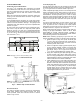
High-Voltage Connections (Fig. 13)
The unit must have a separate electrical service with a field-
supplied, waterproof, fused disconnect switch mounted at, or
within sight from, the unit. Refer to the unit rating plate for
maximum fuse/circuit breaker size and minimum circuit
amps (ampacity) for wire sizing. Table 2 shows recommended
wire sizes based on rating plate data.
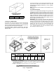
The field-supplied disconnect switchbox may be mounted on
the unit over the high-voltage inlet hole in the control corner
panel. Be sure that disconnect box and horizontal ducts do
not cover the unit rating plate.
Proceed as follows to complete the high-voltage connections
to the unit:
1. Connect ground lead to chassis ground connection
when using separate ground wire.
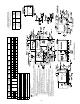
2. Pigtails are provided for field power connection. Use
factory-supplied splices or UL (Underwriters’ Labora-
tories) approved copper connector. Install conduit
connectors in side panel power supply knockout open-
ings indicated in Fig. 3. Route power lines through
connector to unit control box.
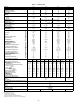
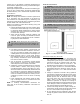
Table 2 — Electrical Data
LEGEND
*Used to determine minimum disconnect per NEC.
†Fuse or HACR circuit breaker.
NOTES:
1. In compliance with NEC requirements for multimotor and combina-
tion load equipment (refer to NEC Articles 430 and 440), the overcur-
rent protective device for the unit shall be fuse or HACR breaker.
Canadian units may be fuse or circuit breaker.
2.
Unbalanced 3-Phase Supply Voltage
Never operate a motor where a phase imbalance in supply voltage is
greater than 2%.
Use the following formula to determine the percent
of voltage imbalance.
% Voltage Imbalance
Example:
Supply voltage is 460-3-60.
AB = 452 v
BC = 464 v
AC = 455 v
= 457
NOTE:
The 575-v 48TJ008-014 units are UL, Canada only.
Determine maximum deviation from average voltage.
(AB) 457 – 452 = 5 v
(BC) 464 – 457 = 7 v
(AC) 457 – 455 = 2 v
Maximum deviation is 7 v.
Determine percent of voltage imbalance.
% Voltage Imbalance = 100 x
= 1.53%
This amount of phase imbalance is satisfactory as it is below the maxi-
mum allowable 2%
IMPORTANT:
If the supply voltage phase imbalance is more than 2%,
contact your local electric utility company immediately.
UNIT
580D
NOMINAL
VOLTAGE
IFM
TYPE
VOLTAGE
RANGE
COMPR
(ea)
OFM
(ea)
IFM
COMBUSTION
FAN MOTOR
FLA
POWER SUPPLY
DISCONNECT
SIZE*
Min Max RLA LRA Hp FLA FLA MCA MOCP† FLA LRA
090
(7
1
/
2
Tons)
208/230-3-60
Std
187 254 14.0 91.0
1
/
4
1.4
5.8
.6
40.1/40.1 45/45 42/42 229/229
Alt 5.8 40.1/40.1 45/45 42/42 229/229
460-3-60
Std
414 508 6.4 42.0
1
/
4
0.7
2.6
.3
18.4 20 19 108
Alt 2.6 18.4 20 19 108
575-3-60
Std
518 632 5.2 39.0
1
/
4
0.7
2.6
.3
14.9 20 16 97
Alt 2.6 14.9 20 16 97
102
(8
1
/
2
Tons)
208/230-3-60 Std 187 254 16.0 137.0
1
/
4
1.4 5.8 .6 44.6/44.6 50/50 41/41 321/321
460-3-60 Std 414 508 8.3 69.0
1
/
4
0.7 2.6 .3 22.7 25 24 162
575-3-60 Std 518 632 6.4 58.0
1
/
4
0.7 2.6 .3 17.6 20 18 135
120
(10 Tons)
208/230-3-60
Std
187 254 15.8 130.0
1
/
4
1.4
5.8
.6
44.2/44.2 50/50 46/46 307/307
Alt 7.5 45.9/45.9 50/50 48/48 326/326
460-3-60
Std
414 508 7.9 64.0
1
/
4
0.7
2.6
.3
21.8 25 23 152
Alt 3.4 22.6 25 24 191
575-3-60
Std
518 632 6.6 52.0
1
/
4
0.7
2.6
.3
18.9 25 20 126
Alt 3.4 19.7 25 21 166
150
(12
1
/
2
Tons )
208/230-3-60
Std
187 254 23.0 146.0
1
/
4
1.4
10.6
.6
65.2/65.2 80/80 68/68 383/383
Alt 15.0 69.6/69.6 80/80 73/73 406/406
460-3-60
Std
414 508 10.4 73.0
1
/
4
0.7
4.8
.3
29.6 35 31 192
Alt 7.4 32.2 35 34 203
575-3-60
Std
518 632 8.3 58.4
1
/
4
0.7
4.8
.3
23.6 30 25 154
Alt 7.4 25.7 30 27 163
FLA —
Full Load Amps
HACR —
Heating, Air Conditioning and Refrigeration
IFM —
Indoor (Evaporator) Fan Motor
LRA —
Locked Rotor Amps
MCA —
Minimum Circuit Amps
MOCP—
Maximum Overcurrent Protection
NEC —
National Electrical Code
OFM —
Outdoor (Condenser) Fan Motor
RLA —
Rated Load Amps
= 100 x
max voltage deviation from average voltage
average voltage
Average Voltage =
452 + 464 + 455
3
=
1371
3
7
457