
User`s manual


—
4
—
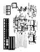
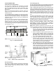
Fig. 4 — Roof Curb Dimensions
“B” “C”
“D” ALT
DRAIN
HOLE
“E”
GAS
“F”
POWER
“G”
CONTROL
CONNECTOR
PACKAGE
ACCESSORY
2
′
-8
7
/
16
″
[827]
1
′
-10
15
/
16
″
[583]
1
3
/
4
″
[44.5]
3
/
4
″
[19] NPT
3
/
4
″
[19] NPT
1
/
2
″
[12.7]
CRBTMPWR001A00
1
1
/
4
″
[31.7]
CRBTMPWR002A00
1
/
2
″
[12.7] NPT
3
/
4
″
[19] NPT
1
/
2
″
[12.7]
CRBTMPWR003A00
3
/
4
″
[19] NPT
1
1
/
4
″
[31.7]
CRBTMPWR004A00
NOTES:
1. Roof curb accessory is shipped unassembled.
2. Insulated panels.
3. Dimensions in [ ] are in millimeters.
4. Roof curb: galvanized steel.
5. Attach ductwork to curb (flanges of duct rest on
curb).
6. Service clearance 4 ft on each side.
7. Direction of airflow.
8. Connector packages CRBTMPWR001A00 and
002A00 are for thru-the-curb connections.
Packages CRBTMPWR003A00 and 004A00
are for thru-the-bottom connections.
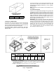
ROOF CURB
ACCESSORY
“A”
UNIT SIZE
580D
CRRFCURB003A00
1
′
-2
″
[356]
090-150
CRRFCURB004A00
2
′
-0
″
[610]