Rev A HEAVY DUTY HYDRAULIC SELF-PROPELLED WALK BEHIND SCRAPER INSTRUCTION MANUAL Caution: Read Manual Before Operating Machine
Table of Contents Table of Contents ................................................................................................................................................................................................... 3 Features and Specificatons ................................................................................................................................................................................... 4 Safety ..............................................................
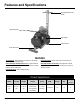
Features and Specifications Quick Adjust Multi Position Handle Lifting Ball Eyebolts Slide Weights Traction Wheels Unique Swivel Head FEATURES Traction Wheels - These industrial grade wheels are self-cleaning and disengage for loading/unloading. Unique Swivel Head - Unique swivel head provides continuous contact with the floor. Side Slide Weights with Quick Adjust Levers - Applies additional pressure to the scraper head as desired or if more traction is needed, slide them back over the wheels.
Safety GENERAL RULES FOR SAFE OPERATION READ AND SAVE ALL INSTRUCTIONS FOR FUTURE USE. Before use, ensure operators reads and understand this manual. Read and understand labeling on machine and components. All operators must view the instruction video. Extra copies of the manual and video are available by contacting National Flooring Equipment. 1. KNOW YOUR EQUIPMENT: Read this manual carefully to learn equipment applications and limitations, potential hazards associated with this type of equipment.
Safety only identical National replacement parts. 24. STORE IDLE EQUIPMENT: When not in use, store in a dry, secured place. Keep away from children. 25. MAINTAIN LABELS AND NAMEPLATES: These carry important information. If unreadable or missing, contact National for a replacement. 26. MACHINE IS HEAVY, DO NOT DROP. Ensure proper lifting procedures are followed when transporting. 27. DO NOT ALLOW the oscilating plates to come into contact with the supply cord. 28.
Safety CAUTION: NEVER USE YOUR HANDS TO CHECK FOR LEAKS OVER HOSE OR HYDRAULIC CONNECTIONS. USE A PIECE OF CARDBOARD TO LOCATE A PRESSURIZED LEAK. FOR LOW PRESSURE LEAKS (DRIPS), USE A RAG TO CLEAN THE AREA AND DETERMINE WHERE THE LEAK ORIGINATES. 3. BURST: Whether due to improper selection or damage, a ruptured hose can cause injury. If it bursts, a worker can be burned, cut, injected or may slip and fall. 4.
Safety The smaller the gauge number of the wire, the greater the capacity of the cord. For example, a 10 gauge cord can carry a higher current than a 12 gauge cord. When using more than one extension cord to make up the total length, be sure each cord contains at least the minimum wire size required. If you are using one extension cord for more than one tool, add the nameplate amperes and use the sum to determine the required minimum wire size.
Machine Operation TRANSPORTING WHEELS ENGAGING OR DISENGAGING Wheels engage and disengage for easier maneuverability. Wheels in the “engage mode” are secured with the axle pins (See Figure B). This engages the wheels for the machine to be self-propelled. When wheels are in the “disengage mode” (See Figure C). Machine can be moved around freely when the machine IS NOT under power. DISENGAGING WHEELS FIG. B Pull up on end of pin to release. Slide pin out. Repeat on second wheel.
Machine Operation RAMP LOADING 1. 2. 3. 4. Put the wheels in “engage mode”. Make sure ramp is clean and dry, free of grease or oil. Position ramp securely to back of vehicle, making sure there is good contact (See Figure G). Position machine at bottom of ramp (See Figure H). 5. Engage power switch and drive onto vehicle. RAMP UNLOADING FIG. G 1. 2. 3. 4. Put the wheels in “engage mode”. Position ramp securely to back of vehicle, making sure there is good contact (See Figure G).
Machine Operation ANGLE ATTACHMENTS 7280-2B STEEP ANGLE ATTACHMENT 22° The angle attachments angles the cutting head and blade or carbide shank to where the material comes up the easiest. Lower is usually the best. MOUNTING ANGLE ATTACHMENT • Disconnect machine from power source. • Tilt machine back. • Securely block machine up (See Figure M). • Insert desired cutting head or carbide shank into the angle attachment. 22° FIG.
Machine Operation PREPARING MACHINE FOR JOB BLADE SETTING Note: The 6280HD is designed for soft goods and most hard good removal applications. • Proper blade size and placement, depending on material and sub-floor type, affects performance. • The harder a job comes up, for best results, use a smaller blade. • Start with a narrow blade, then increase blade size to optimize cutting pass. Narrower blades work easier than wider blades and usually clean the floor better.
Machine Operation BLADE SHARPENING Dull blades greatly reduce cutting ability. Re-sharpen or replace as needed. In use, blades develop a back-bevel (Figure U). When re-sharpening, blade will not be truly sharp until all back-bevel is gone. Note: Thinner blades are easier to sharpen, but they also break easier. • Always wear gloves and safety glasses. • Grind blade using a 4” diameter disk with 120 or finer grit. Be careful not to catch disk on edge or corner of blade.
Machine Operation keep the blade sharp. Use a sharper angle of attack if necessary. SUBFLOOR SURFACES FIG. W Glued Hard Wood Flooring: A 10” (25.4 cm) blade is recommended for regular adhesive, a 6” (15.25 cm) blade for epoxy. For proper removal of hardwood flooring (plank solid, plank laminated, parkay laminated), flooring must be scored to blade width.
Blades HEAVY DUTY BLADES (FIGURE Y) This heavy duty blade is flexible and delivers jobsite versatility. Made with National’s proven blade hardening process, these blades will stay sharper longer with better overall performance than any other blade on the market. They work on VCT, VAT, wood, tile, rubber, epoxy, elastomeric coatings, scraping thin-set and glued ceramic. PART# 6283 6284 6285 6286 DESCRIPTION THICKNESS (IN.
Blades TAPERED CUTTING HEAD SHANKS (FIGURE CC) The longer taper works great on tough wood floors (glued & nailed). The long length allows the blade to easily slide under tough materials. They work through most ceramics and VCT. PART# DESCRIPTION THICKNESS (IN.) 7075-8 2’’ X 8’’ TAPERED CUTTING HEAD SHANK .300 7077-8 3.5” X 8’’ TAPERED CUTTING HEAD SHANK .300 FIG. CC Fax: 763-535-8255 16 info@nationalequipment.
Machine Maintenance WARNING: ALWAYS UNPLUG MACHINE BEFORE MAINTAINING. WHEEL CLEANER ADJUSTMENT Wheel Cleaner 1. Loosen wheel cleaner with 9/16” wrench (See Figure DD). 2. Slide cleaner up to face of wheel until it touches but DOES NOT dig into wheel surface. 3. Retighten firmly. 4. Over tightening wheel cleaner will damage wheel. FIG. DD WHEEL REMOVAL 1. Unplug machine. 2. Examine back of wheels for built-up debris. 3. Remove yarn build up. 4. Lay machine on its side. 5.
Machine Maintenance TANK REMOVAL Removing the tank will be necessary to repair the pump or to replace or service internal hoses. FIG. HH 1. Drain tank by removing top Filler Port Cap and Drain Plug on side of machine (See Figure HH). A container approximately two gallons in size will be needed to drain fluid into. 2. Replace Drain Plug and Filler Port Cap. 3. Remove two lifting bail eyebolts and the two bolts from the back of the tank. 4.
Troubleshooting Guide Problem Cause Solution No Forward or Reverse a. Check wheel pins b. Check belt & chain a. Check to make sure wheel pins are in the wheels b. Check belt & chain by removing front cover and inspecting Motor shuts off or will not start Electric box needs reset. Press reset button located on electric box on motor. Wheels do not turn when machine is under power Axle pins out of place. Check axle pins and make sure they are in place Motor Problems (humming etc.) a.
Complete Parts List PART# DESCRIPTION 1 2 3 4 5 6 7 8 9 10 11 12 13 14 15 16 17 18 19 20 21 22 23 24 25 26 27 28 29 30 31 32 33 34 35 36 74853-G L95K L95J L95H L95G L95F L95E L95D L95C L49 L37 L223 L190 L189 L188 L187 L186 L177 L175 L141 74851 7280-4B 7280-4 7280-2 6280HD-400 6280HD-228 6280HD-225 6280HD-212 6280HD-210 6280HD-203 6280HD-202 6280HD-183 6280HD-182 6280HD-181 6280HD-180 6280HD-17 37 38 39 40 41 42 43 44 45 46 47 48 49 50 51 52 53 6280HD-167D 6280HD-167C 6280HD-167 6280HD-165 6280HD-164-1
Complete Parts List PART# 103 73412 104 73405 105 73403 106 73402 107 73330 108 73318 109 73314 110 73311 111 73310 112 113 114 115 116 117 118 119 120 121 122 123 124 125 126 73306 73304 73270 73259 73238 73228 73223 73222 73220 73219 73218 73217 73215 73211 73206 DESCRIPTION QTY PART# 1/2-13 X 4-1/2 HEXHEAD BOLT 2 1/2-20 STAR WASHER 9 WASHER, SPLIT LOCK 1/2 2 1/2-13 NYLOCK NUT 2 5/16 X 2 PIN 1 5/16-18 X 5/8 WIZLOCK BOLT 8 5/16-18 X 3/8 FLAT HEAD CAP SCREW 2 5/16-18 X 1 SOCKET HEAD CAP SCREW,LEFT, G
Parts List and Diagrams EXTERNAL PARTS 10 6 14 15 9 13 12 7 1 5 2 11 3 4 PART# 1 2 3 4 5 6 7 8 74853-BLK 74851 6280HD-146 6280HD-146A 6280HD-165 73019 73203 73219 Fax: 763-535-8255 DESCRIPTION QTY SIDE WEIGHT SLIDE WEIGHT FRONT COUNTERWEIGHT ADD-ON FRONT COUNTERWEIGHT WHEEL CLEANER 1/4-20 X 3/4 HEXHEAD BOLT 3/8 FLAT WASHER 3/8-16 X 5 HEXHEAD BOLT (NOT SHOWN) PART# 2 2 1 1 1 4 6 4 9 10 11 12 13 14 15 22 73220 73228 73238 73270 73426 73403 73424 DESCRIPTION QTY 3/8-16 X 3 HEXHEAD BOLT 3/8-
Parts List and Diagrams BASE PLATE PARTS 6 7 2 3 3 6 7 1 4 5 3 6 7 PART# 1 2 3 4 6280HD-107 6280HD-108 70810 73201 DESCRIPTION BASE PLATE PUMP DRIVE BELT CUTTING HEAD VIBRATION ISOLATOR 3/8-16 X 1HEXHEAD BOLT, GRADE 5 www.nationalequipment.
Parts List and Diagrams PART# IDLER ASSEMBLY PARTS 1 5 6 3 4 4 1 2 3 4 5 6 7 6280-125 6280-125W 6280-126A 71072 73003 73215 73218 DESCRIPTION QTY IDLER ASSEMBLY COMPLETE IDLER MOUNTING BRACKET & PIN IDLER BEARING CAP 1/2″ ID BEARING 1/4-20 X 5/8 BUTTON HEAD SCREW 3/8 EXTERNAL LOCK WASHER 3/8-24 X 3/4 HEXHEAD BOLT, GRADE 5 1 1 1 2 1 1 1 7 3 PUMP DRIVE ASSEMBLY PARTS 5 3 4 2 1 PART# 1 2 3 4 5 6 7 6280-116A 6280-103A 6280HD-14 6280HD-15 6280HD-17 71115 73101 DESCRIPTION QTY PUMP SHAFT SPLI
Parts List and Diagrams PART# 1 2 3 4 5 6 7 8 9 6280-156R 6280-156L 6280HD-139 73222 73506 73311 73318 73402 73412 DESCRIPTION BODY PARTS QTY RIGHT UPPER MAIN BODY LEFT UPPER MAIN BODY REAR COVER 3/8-16 X 1 WIZLOCK BOLT (TANK) 3/8 90° CABLE CONNECTOR 5/16-18 X 1 SOCKET HEAD CAP SCREW 5/16-18 X 5/8 WIZLOCK BOLT 1/2-13 NYLOCK NUT 1/2-13 X 4-1/2 HEXHEAD BOLT 1 1 1 4 1 4 2 2 2 2 1 5 6 6 4 7 9 PART# 1 2 3 4 6280HD-138 71118 73211 73318 DESCRIPTION MAIN BOTTOM COVER 1” ID FLANGE BEARING 3/8-16 WIZLO
Parts List and Diagrams AXLE ASSEMBLY PARTS 6 PART# 11 3 7 2 1 4 8 9 2 1 2 3 4 5 6 7 8 9 10 6280-104A 6280HD-102 6280HD-103 6280HD-104 6280HD-105L 6280HD-105R 71128 73010 73012 73310 11 73311 7 DESCRIPTION QTY AXLE SPROCKET KEY 1 AXLE SNAP RING 1-1/8 2 DRIVE AXLE 1 AXLE SPROCKET ONLY (KEY SOLD SEPARATELY) 1 AXLE BEARING SUPPORT, LEFT 1 AXLE BEARING SUPPORT, RIGHT 1 1⅛″ BEARING 2 1/4-20 X 1/4 SET SCREW 1 1/4-20 X 3/8 SET SCREW 1 5/16-18 X 7/8 SOCKET HEAD CAP SCREW, RIGHT, GRADE 5 2 5/16-18 X
Parts List and Diagrams PART# 1 2 3 4 5 6 7 8 9 10 11 12 DESCRIPTION 6280-208A 6280HD-150 6280HD-151 6280HD-164-1 6280HD-210 6280HD-212 72801 73002 73009 73016 73018 74402 SPEED CONTROL KNOB ONLY VALVE BLOCK ASSEMBLY FILTER VALVE BLOCK COVER SOLENOID-110VOLT (NOT SHOWN) SPEED CONTROL CARTRIDGE HOSE FITTINGS (NOT SHOWN) 1/4-20 SPLIT WASHER 1/4-20 HEX NUT 1/4-20 X 5/8 HEXHEAD BOLT 1/4-20 X 3 HEXHEAD BOLT 10-32 X 3/8 SET SCREW INTERNAL HANDLE PARTS QTY 1 1 1 1 1 1 2 7 1 4 3 1 9 4 6 1 12 11 3 8 7 8 10
Parts List and Diagrams HOSE PARTS PART# 1 2 3 4 4 6280HD-180 6280HD-181 6280HD-182 6280HD-183 DESCRIPTION QTY LOWER MOTOR HOSE PUMP HOSE UPPER MOTOR HOSE PUMP HOSE TO BLOCK HOSE 1 1 1 1 2 1 3 PART# TANK PARTS 1 6280-161B 2 6280HD-162 3 70601 DESCRIPTION QTY FILLER CAP VENT PLUG ONLY HYDRAULIC TANK TANK MOUNTED STRAINER 1 1 1 2 1 Fax: 763-535-8255 3 28 info@nationalequipment.
Parts List and Diagrams MOTOR PARTS 1 2 8 4 3 5 9 10 11 PART# 1 2 3 4 5 6 6280-147-1 6280-148A 6280-150 6280-152 6280-152-1 6280-152-3 7 6280-152-4 8 6280HD-202 DESCRIPTION QTY STARTER SWITCH MOTOR FAN COVER SCREW CAPACITOR COVER MOTOR JUNCTION BOX ONLY MOTOR JUNCTION BOX COVER ONLY MOTOR JUNCTION BOX COVER GASKET ONLY (NOT SHOWN) MOTOR JUNCTION BOX GASKET (NOT SHOWN) MOTOR CAPACITOR (RUN) www.nationalequipment.
Parts List and Diagrams PART# CUTTING HEAD PARTS 3 1 7 6 7 6 1 2 3 4 5 6 7 6280HD-1 6280HD-145 71141 73222 73306 73405 73418 DESCRIPTION QTY CUTTING HEAD BASE PLATE FRONT COVER 1-7/16″ ID BEARING 3/8-16 X 1 WIZLOCK BOLT (BASE PLATE) 5/16-18 X 1/2 HEXHEAD BOLT 1/2-20 STAR WASHER 1/2-20 X 1 HEXHEAD BOLT 1 1 1 5 2 9 9 4 5 5 2 PART# WHEEL SECURING PARTS 1 2 1 2 3 4 5 RETAINER CAP ASSEMBLY 5/16 X 2 PIN RETAINER CAP O-RING RETAINER CAP HEXHEAD BOLT RETAINER CAP ONLY 1 1 1 1 1 4 PART# SWITCH PART
Parts List and Diagrams INTERNAL PARTS 1 12 4 7 7 3 8 6 16 17 9 17 5 14 15 13 10 PART# 1 2 3 4 5 6 7 8 9 6280-113S 6280-113-1 6280-117 6280-118 6280-119 6280-120 6280-221 6280-223 6280-225 DESCRIPTION QTY PART# PUMP SPLINED 1 SEAL KIT (NOT SHOWN) 1 PRESSURE HOSE TO PUMP CONNECTOR 1 SUCTION HOSE TO PUMP CONNECTOR 1 PUMP SPACER 1 SUCTION HOSE 1 HYDRAULIC MOTOR CONNECTOR 2 HYDRAULIC MOTOR SHAFT KEY 1 HYDRAULIC MOTOR SPACER 1 www.nationalequipment.
Parts List and Diagrams LABELS 1 8 2 5 6 10 9 11 4 3 7 (on each side) PART# 1 2 3 4 5 6 L95C L95D L95E L95F L95G L95J Fax: 763-535-8255 DESCRIPTION FORWARD LABEL REVERSE LABEL SPEED CONTROL LABEL WARNING FLUID LEAK LABEL FLUID LEVEL LABEL 110 VOLT LABEL (NOT SHOWN) QTY PART# 1 1 1 1 1 1 7 8 9 10 11 32 L95K L186 L187 L188 L189 DESCRIPTION QTY RAMP LABEL ON/OFF SWITCH LABEL REMOVE COUNTERWEIGHTS LABEL CAUTION GENERAL INFO LABEL ASBESTOS LABEL 2 1 1 1 1 info@nationalequipment.
Parts List and Diagrams LABELS (CONT’D) 1 3 2 7 5 6 4 8 PART# 1 2 3 4 5 6 L37 L49 L95H L141 L175 L177 DESCRIPTION CAUTION SHARP BLADE LABEL POWER CORD LABEL CAUTION DO NOT RUN LABEL MADE IN USA LABEL NATIONAL LABEL, SMALL STOCK NUMBER LABEL www.nationalequipment.
Parts List and Diagrams LOADING RAMP Durable light weight construction. Folds for easy transportation and storage. TRANSPORT WHEELS 6251 Loading Ramp 6251-1 Replacement Pinch Point Guard (Set) Allows stability and safe transportation over any surface. Easy and quick to attach. 6280HD-250 Transport Wheels 6280-301 Replacement Wheel Only 73330 Securing Pin Only 50’ POWER CORD 50’ 12 Gauge Power Cord 6254 Fax: 763-535-8255 34 50’ Power Cord info@nationalequipment.
Parts List and Diagrams 6280HD WIRING DIAGRAM www.nationalequipment.
Fax: 763-535-8255 B HYDRAULIC MOTOR A REV. PRESS. FLOW T P 36 POSITIVE PRESSURE FWD. PRESS. FLOW A HYDRAULIC VALVE B TO TOP OF TANK. HYD. PUMP FLUID TANK BLEED SUCTION (NEGATIVE PRESS.) Parts List and Diagrams 6280HD HYDRAULIC LINE LAYOUT info@nationalequipment.
Material Safety Data Sheet (MSDS) Information CHEVRON HD 22 - 68 - HYDRAULIC FLUID PRODUCT IDENTIFICATION AND COMPANY IDENTIFICATION Product Number(S): CPS221655, CPS221658, CPS221659 Synonyms: Texaco Rando HD22, Texaco Rando HD 32, Texaco Rando HD 46, Texaco Rando HD 68 Company Information Chevron Products Company a division of Chevron U.S.A. Inc. 6001 Bollinger Canyon Road San Ramon, CA 94583 United States of America www.chevronlubricants.
Material Safety Data Sheet (MSDS) Information CHEVRON HD 22 - 68 - HYDRAULIC FLUID (CONTINUED) EXTINGUSHING MEDIA: Use water fog, foam, dry chemical or carbon dioxide (CO2) to extinguish flames. PROTECTION OF FIRE FIGHTERS: Fire Fighting instructions: This material will burn although it is not easily ignited. For fires involving this material, do not enter any enclosed or confined fire space without proper protective equipment, including self-contained breathing apparatus.
Material Safety Data Sheet (MSDS) Information CHEVRON HD 22 - 68 - HYDRAULIC FLUID (CONTINUED) PHYSICAL AND CHEMICAL PROPERTIES Attention: The data below are typical values and do not constitute a specification. Color: Yellow Physical State: Liquid pH: Not applicable Vapor Pressure: <0.01 mmHg @ 37.8 C (100 F) Boiling Point: >315.6 C (600 F) Solubility: Soluble in hydrocarbons; insoluble in water Melting Point: Not Applicable Specific Gravity: 0.86 - 0.87 @ 15.6 C (60.1 F) / 15.6 (60.
Material Safety Data Sheet (MSDS) Information REGULATORY INFORMATION EPCRA 311/312 CATAGORIES: 1. Immediate (Acute) Health Effects: NO 3. Fire Hazard: NO 5. Reactivity Hazzard: NO 2. Delayed (Chronic) Health Effects: NO 4. Sudden Release of Pressure Hazard: NO REGULATORY LISTS SEARCHED: 01-1=IARC Group1 03=EPCRA 313 01-2A=IARC Group 2A 04=CA Proposition 65 01-2B=IARC Group 2 05=MA RTK 02=NTP Carcinogen 06=NJ RTK No components of this material were found on the regulatory lists above.
Guarantee National Flooring Equipment, Inc. (National) warrants to the first consumer/purchaser that this National brand product 6280 Heavy Duty SelfPropelled Walk Behind Scraper when shipped in its original container, will be free from defective workmanship and materials and agrees that it will, at its option, either repair the defect or replace the defective product or part thereof at no charge to the purchaser for parts or labor for the period(s) set forth below.
9250 Xylon Avenue N • Minneapolis, MN 55445 • U.S.A. Toll-free 800-245-0267 • Phone 763-315-5300 • Fax 800-648-7124 • Fax 763-535-8255 Web Site: www.nationalequipment.com • E-Mail: info@nationalequipment.