Operator’s Manual Ingersoll Rand’s Climate Solutions sector delivers energy-efficient HVACR solutions for customers globally. Its world class brands include Thermo King, the leader in transport temperature control and Trane, a provider of energy efficient heating, ventilating and air conditioning systems, building and contracting services, parts support and advanced controls for commercial buildings and homes.
T-680R / T-880R / T-1080R T-680S / T-880S / T-1080S Series with Standard SR-3 HMI TK 55665-1-OP (Rev. 1, 02/2015) Copyright© 2013 Thermo King Corp.
Disclaimer This manual is published for informational purposes only. Thermo King Corporation makes no representations or warranties, express or implied, with respect to the information, recommendations and descriptions contained in this manual and such information, recommendations and descriptions should not be regarded as all-inclusive or covering all contingencies. In the event you have any questions or require further information, please contact your local Thermo King dealer.
Table of Contents Introduction . . . . . . . . . . . . . . . . . . . . . . . . . . . . . . . . . 6 Safety Precautions . . . . . . . . . . . . . . . . . . . . . . . . . . . 7 Automatic Start/Stop Operation . . . . . . . . . . . . . . . . . . 7 Battery Installation and Cable Routing . . . . . . . . . . . . . 8 Electrical Hazard . . . . . . . . . . . . . . . . . . . . . . . . . . . . . . 9 Refrigerant . . . . . . . . . . . . . . . . . . . . . . . . . . . . . . . . . . 9 Refrigerant Oil . . . . . . . . . . . .
Table of Contents DAS - Data Acquisition System (Optional) . . . . . . . . . 29 CargoLink (Optional) . . . . . . . . . . . . . . . . . . . . . . . . . . 30 Electric Standby (Model 50 Units Only) . . . . . . . . . . . . 30 Standard Model 50 Features . . . . . . . . . . . . . . . . 31 Optional Model 50 Features . . . . . . . . . . . . . . . . . 31 Engine Compartment Components . . . . . . . . . . . . . . . 31 Unit Protection Devices . . . . . . . . . . . . . . . . . . . . . . . . 32 Unit Operation . . . . .
Table of Contents Electric Standby Operation . . . . . . . . . . . . . . . . . . . 72 Electric Power Receptacle . . . . . . . . . . . . . . . . . . . . . 72 Loading and Enroute Inspections . . . . . . . . . . . . . . Pre-Loading Inspection . . . . . . . . . . . . . . . . . . . . . . . . Inspecting the Load . . . . . . . . . . . . . . . . . . . . . . . . . . . Enroute Inspections . . . . . . . . . . . . . . . . . . . . . . . . . . 73 73 74 75 Specifications . . . . . . . . . . . . . . . . . . . . . . . .
Introduction There is nothing complicated about operating and maintaining your Thermo King unit, but a few minutes studying this manual will be time well spent. Performing pre-trip checks and enroute inspections on a regular basis will minimize on-the-road operating problems. A regular maintenance program will also help to keep your unit in top operating condition.
Safety Precautions Thermo King recommends that all services be performed by a Thermo King dealer. However, there are several general safety practices which you should be aware of: WARNING: Always wear goggles or safety glasses when working with or around the refrigeration system or battery. Refrigerant or battery acid can cause permanent damage if it comes in contact with your eyes.
Safety Precautions Battery Installation and Cable Routing WARNING: Improperly installed battery could result in a fire or explosion! A Thermo King approved battery must be installed and properly secured to the battery tray. WARNING: Improperly installed battery cables could result in fire or explosion! Battery cables must be installed, routed and secured properly to prevent them from rubbing, chaffing or making contact with hot, sharp or rotating components.
Safety Precautions Electrical Hazard CAUTION: Be sure to turn off the high voltage power supply, and disconnect the electric cable before working on the unit. Units with electric standby present a potential electrical hazard. Refrigerant Although fluorocarbon refrigerants are classified as safe, observe caution when working with refrigerants or around areas where they are being used in the servicing of your unit. DANGER: Fluorocarbon refrigerants may produce toxic gases.
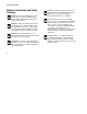
Safety Precautions First Aid First Aid–Refrigerant Eyes: For contact with liquid, immediately flush eyes with large amounts of water. Get prompt medical attention. Skin: Flush areas with large amounts of warm water. Do not apply heat. Wrap burns with dry, sterile, bulky dressing to protect from infection or injury. Get prompt medical attention. Inhalation: Move victim to fresh air and restore breathing if necessary. Stay with victim until arrival of emergency medical personnel.
Safety Precautions Safety Decals and Locations AKA98 Figure 2: Belt Caution (Locations vary depending on model. Decals are located near areas that contain belts and fans which can cause severe injuries if hands or clothing become tangled.) Figure 1: Antifreeze Caution (Attached near radiator fill cap.
Safety Precautions CAUTION FAN ACHTUNG VENTILATOR 91-4815 ATTENTION VENTILATEUR ATTENZIONE VENTILATORE AKA99 CUIDADO VENTILADOR ARA183 Figure 3: Automatic Start Caution (Locations vary depending on model. Decals are located near areas that contain moving parts which can cause severe injuries if hands or clothing become tangled when the unit automatically starts.) 12 Figure 4: Fan Caution (Locations vary depending on model.
Safety Precautions SmartPower Units (Electric Standby) AKB01 AKB02 Figure 5: Electrical Hazard (Locations vary depending on model. Typically located near power receptacle, high voltage tray cover and interface board.) Figure 6: High Voltage Caution (Located near high voltage box.
Emission Control In compliance with the California ULG (Utility, Lawn and Garden) Rules, the following information is provided: 1. Selection Of Fuel Oil: Use diesel fuel only. 2-1. Modification To Any Engine Component: Modifications to any engine component which many cause engine exhaust emission output changes are not allowed. Any engine modification not in compliance with regulation will be the responsibility of the engine manufacturer, dealer or customer who made the modification. 2-2.
Emission Control a. Emission control label: a new label, shown in Figure 7, contains important engine information. AMA04 b. Engine Family Name, as assigned by the California Air Resources Board, identifies engine family group, by largest displacement, within an engine family, and is shown in Figure 8.
Emission Control 3-1 Emission Control Labels: Emission control labels are a requirement of the California ULG Rules.
Emission Control 4. Emission Control Related Parts: The California ULG Rules require a manufacturing defect warranty on all emission control parts, including: 5. Maintenance Schedule: To maintain optimum engine performance and compliance with the California ULG Rules, the maintenance schedule must be adhered to. • Fuel Injection Pump • Fuel Injection Nozzle • High Pressure Oil Line Regular scheduled maintenance is the major key to engine service life and emission regulation compliance.
Emission Control (ULG) engine for the time listed below, provided there has been no abuse, neglect or improper maintenance of your utility equipment (ULG) engine. Your California emission control system includes parts such as the fuel injection pump, the fuel injection nozzle, and the high-pressure fuel line. Also included are the air filter element and the fuel filter element which are covered under this California emission control system warranty only up to the first scheduled maintenance replacement.
Emission Control Manufacturer Explanation Of Emission Control System Warranty Coverage at a Thermo King authorized service dealer. To obtain the phone number of your nearest Thermo King authorized service dealer, call the Cold Line at: 952-887-2202. 2.
Emission Control D. What is Not Covered 1. Failures caused by abuse, neglect, or improper maintenance. 2. Add-On or Modified Parts. The use of add-on or modified parts can be grounds for disallowing a warranty claim. Thermo King is not liable for failures of emission control system parts or components caused by the use of add-on or modified parts. 3.
Emission Control EPA Emission Control System Warranty Statement Thermo King warrants to the initial owner and each subsequent owner that the certified non-road diesel engine in your unit is: 1. Designed, built and equipped so as to conform, at the time of sale, with all applicable regulations adopted by the United States Environmental Protection Agency (EPA). 2.
Emission Control This warranty covers the following emission-related parts and components: NOTE: Items replaced under this warranty become the property of Thermo King. • Fuel Injection System • • Intake Manifold • Exhaust Manifold • Miscellaneous hoses, clamps, connectors and sealing devices used in the above systems. If failure of one of these parts or components results in failure of another part or component, both will be covered by this warranty.
Emission Control Limitations Thermo King is not responsible for resultant damages to an emission-related part or component resulting from: • Any application or installation Thermo King deems improper as explained in this Operator’s Manual, or any other manuals provided with the unit. • Attachments, accessory items, or parts not authorized for use by Thermo King. • Improper off-road engine maintenance, repair, or abuse.
Unit Description General Description Units are offered as Model 30 or Model 50: This manual covers the following Thermo King models: Model 30: Cooling and hot gas heating on engine operation. • T-680R, T-880R and T-1080R with reciprocating compressor. • T-680S, T-880S and T-1080S with scroll compressor. Model 50: Cooling and hot gas heating on engine operation and electric standby operation. Electric evaporator heaters are optional.
Unit Description Design Features • Bypass Oil Filter • Microprocessor Controller, SR-3 Truck • Coolant Expansion Tank • Alarm Code Display • Diesel/Electric Autoswitching (Model 50) • Battery Voltage Display • Economy Mode • Continuous System Monitoring • Fahrenheit and Celsius Scales • Coolant Temperature Display • Fuel Filter, Spin On • CYCLE-SENTRYTM Start/Stop Controls • Low Decibel Kit • Engine and Electric (Model 50) Hour Display • Oil Filter, Full Flow • In-Cab Remote
Unit Description • Stainless Steel Condenser and Evaporator Hardware • Quick Oil Drain Kit • TK374F Tier 4 Diesel Engine (T-680R, T-680S, T-880R and T-880S) • Rear Remote Control (flushmount) • Remote Indicator Light • TK380F Tier 4 Diesel Engine (T-1080R and T-1080S) • Snow Cover • Telematics • Whisper ™ Plus Sound Kit • Top Cover System Unit Options • Body Mount HMI Enclosure Systems • DAS (Data Acquisition System) • Door Switch • CargoLink™ Wireless Sensors • Easy-Read Therm
Unit Description Engine Engine power for the T-680R, T-680S,T-880R and T-880S is provided by the TK374F, a three-cylinder, EPA Tier 4, special clean and quiet diesel engine rated at 11.7 continuous horsepower (8.7 kW) at 2200 RPM. A belt drive system transfers energy to the compressor, unit fans, and alternator. Engine power for the T-1080R and T-1080S is provided by the TK380F, a three cylinder, EPA Tier 4, special clean and quiet diesel engine rated at 16.2 continuous horsepower (12.1 kW) at 2200 RPM.
Unit Description CAUTION: Do not add Green or Blue-Green coolants to cooling systems that use Red Extended Life Coolants. NOTE: The use of 50/50% pre-mixed ELC is recommended to ensure that deionized water is being used. If 100% full strength concentrate is used, deionized or distilled water is recommended instead of tap water to ensure the integrity of the cooling system is maintained. Scroll Compressor The T-680S and T-880S feature the TK04 scroll compressor.
Unit Description WARNING: Turn the unit off by pressing the OFF key before opening doors or inspecting any part of the unit. The unit can start at any time without warning if it has been turned on by pressing the ON key. The CYCLE-SENTRY system automatically starts the unit on microprocessor demand and shuts down the unit when all demands are satisfied.
Unit Description DAS data can be downloaded through a serial port to an IBM® PC compatible computer. WinTrac™ 4.0 (or higher) software is used to view and analyze the data. Brief reports can be printed on a microprinter connected to the serial port. CargoLink™ (Optional) CargoLink™ is a wireless sensor system. The main components are the coordinator module, interconnect harness, antenna, and wireless sensors.
Unit Description Standard Model 50 Features The following features are standard equipment on units equipped with Electric Standby. Automatic Diesel/Electric Selection: The unit will automatically switch to electric operation when a power cord is connected and the standby power is switched On. Overload Relay: The overload relay is self-resetting. Hot Gas Heat: Hot gas heat is utilized on all units.
Unit Description Receiver Tank Sight Glass: The receiver tank sight glass is used to assist in checking the amount of refrigerant in the system. Compressor Oil Sight Glass: The compressor oil sight glass is used to check the relative level of compressor oil in the compressor sump. Unit Protection Devices High Pressure Cutout Switch (HPCO): This normally closed switch monitors the discharge pressure at the compressor. It opens on high discharge pressure to shut the unit down to prevent damage.
Unit Description Figure 13: T-680S Front View (T-680R, T-880S and T-880R are similar) 33
Unit Description Figure 14: T-1080S Front View (T-1080R is similar) 34
Unit Description 2 3 1 4 5 6 7 8 1. Engine Oil Dipstick (on side of engine) 5. Alternator 2. Engine 6. Compressor (reciprocating shown) 3. Coolant Expansion Tank 7. Dehydrator (Filter-Drier) 4. Electric Motor 8.
Unit Operation SR-3 Truck HMI Controller The SR-3 Standard Truck HMI (Human/Machine Interface) Control Panel is supplied as standard equipment on SR-3 Single Temperature Truck applications. It is used to operate the unit and display some unit information. The SR-3 Standard Truck HMI Control Panel communicates with the base controller via the CAN (Controller Area Network) bus. It is connected to the base controller via CAN Connector J14 on the interface board.
Unit Operation • Selects and Indicates CYCLE-SENTRY or Continuous Mode Operation • Selects and Indicates High Speed Lock-Out Operation • Initiates and Indicates a Defrost Cycle • Indicates an Alarm Condition Exists, Displays and Clears Alarms • Initiates and Indicates a Pretrip Test • Sends a Start of Trip to the ServiceWatch data logger. • Changes Display Brightness The upper row of numbers can display the Box Temperature, Engine Run Time Hourmeter or Alarm Code(s).
Unit Operation When this icon is present the lower display is showing the current setpoint. When this icon is present the upper display is showing the diesel engine run time. When this icon is present the lower display is showing the electric motor run time (if the unit equipped with optional ELECTRIC STANDBY). When this Alarm Icon is present one or more alarm conditions have occurred. If the display is not flashing any alarms are Check Alarms.
Unit Operation There are amber indicator LED's located next to each of the four function keys below the display. The LED will glow amber when that function is active. The primary and secondary key uses are shown in the table below. If the key has more than one use the primary use is shown first. A red indicator LED is located between the ON Key and OFF Key at the left side of the display. This indicator will glow if Alarm Code 91 Check Electric Ready Input occurs.
Unit Operation POWER OFF Key Pressing the OFF Key will turn the unit off. UP ARROW Key When the unit is turned on and the Standard Display is shown, pressing the UP ARROW Key will increase the setpoint. Secondary Use - When alarms are being displayed, pressing this key will scroll thru the alarms (if more than one alarm is present). Secondary Use - While holding ON Key down with the unit turned on, pressing this key will increase the display brightness (Low, Medium, High).
Unit Operation ENTER Key If the setpoint has been changed using the UP ARROW Key and/or DOWN ARROW Key, pressing the ENTER Key enters the setpoint into the base controllers memory. Secondary Use - When alarms are being displayed, pressing this key will clear the alarm shown on the display. Secondary Use - When the unit is turned on, press and hold this key for 5 seconds to send a Start of Trip (SOT) to the data logger.
Unit Operation HIGH SPEED LOCK-OUT Key If the unit is turned on, pressing the HIGH SPEED LOCK-OUT Key will activate High Speed Lock-Out. The unit will switch to low speed operation and the amber LED indicator will glow. No further high speed operation is allowed until this feature is turned off. Unit may automatically return to high speed operation after a programmed time limit if timer feature is enabled.This feature is typically used in noise sensitive areas to reduce unit noise.
Unit Operation PRETRIP TEST Key Pressing and holding the PRETRIP TEST Key for 5 seconds will initiate either a Full Pretrip Test or Engine Running Pretrip Test so long as no alarm conditions exist. If the Alarm Icon is glowing, record and clear the alarms before starting the Pretrip Test. Press and hold the PRETRIP TEST Key for 5 seconds. If the unit is not running when the PRETRIP TEST Key is pressed the unit will perform a Full Pretrip that includes circuit amps and running system checks.
Unit Operation Turning the Unit On and Off IMPORTANT: Verify the Base Controller On/Off Switch is turned on before turning on the HMI Control Panel. The Base Controller On/Off switch is located on the outside of the control box side of the unit. If the Standard Truck HMI Control Panel is turned on and the Base Controller On/Off Switch is turned off, the HMI display screen will flash on and off. The unit is turned on by pressing the ON Key and off by pressing the OFF Key.
Unit Operation Figure 20: Electric Motor Run Time Hours and Electric Icon When the unit is ready to run the Standard Display of box temperature and setpoint appears. The box temperature and Box Temp Icon are shown in the upper display. The setpoint and Setpoint Icon are shown in the lower display. The box temperature shown in Figure 21 is 35.8 F (2.1 C) with a 35 F (1.6 C) setpoint. Figure 21: Standard Display of Box temperature and Setpoint Pressing the OFF Key stops unit operation.
Unit Operation The Standard Display Changing the Setpoint The Standard Display is the default display that appears if no other display function is selected. The Standard Display shows the box temperature and setpoint. The box temperature is that measured by the return air sensor. The box temperature and Box Temperature Icon are shown in the upper display. The setpoint and Setpoint Icon are shown in the lower display. The box temperature in Figure 23 is 35.8 F (2.1 C) with a 35 F (1.6 C) setpoint.
Unit Operation • The setpoint display will flash for 10 additional seconds. If at the end of this time the ENTER Key still has not been pressed to complete the setpoint change, the setpoint will return to the old setpoint and Alarm Code 127 Setpoint Not Entered will be set. The Alarm Icon will appear in the display. Figure 26: Alarm Icon and Setpoint Notice that the setpoint has returned to the old setpoint of 35 F (1.
Unit Operation • If the ENTER Key is not pressed within 20seconds of making a change with the UP ARROW Key and/or DOWN ARROW Key, the setpoint is not changed and the display returns to the Setpoint Display showing the old setpoint. Alarm Code 127 Setpoint Not Entered is set and the Alarm Icon will appear on the display, to indicate that the setpoint change was started but not completed.
Unit Operation CAUTION: The motor may start automatically any time the unit is turned on. When the motor is preparing to start, the SR-3 Standard Truck HMI Control Panel will continue to show the Standard Display as shown in Figure 28. The preheat buzzer at the unit (located on the unit Interface Board) sounds for 20 seconds before the electric motor starts. Switching from Diesel to Electric IMPORTANT: Applies to units with the Electric Standby Option only.
Unit Operation Switching from Electric to Diesel IMPORTANT: Applies to units with the Electric Standby Option only. The operation of this feature can be changed using the Guarded Access Menu. See the Guarded Access / Unit Configuration Menu / Electric to Diesel Auto Switch Enabled feature. Electric to Diesel Auto Switch Enabled feature set YES: If this feature is set YES, the unit will switch automatically from Electric Mode to Diesel Mode when standby power is removed or fails.
Unit Operation Figure 31: Display, Preferred Method for Manually Switching from Electric Mode to Diesel Mode Figure 30: Press ON Key Preferred Method for Manually Switching from Electric Mode to Diesel Mode 1. Press the Standard Truck HMI Control Panel OFF Key to turn the unit off. 2. Turn off the standby power and disconnect the cord. 3. Press the Standard Truck HMI Control Panel ON Key to turn the unit on.
Unit Operation To restart the unit in Diesel Mode, proceed as follows: • Press the Standard Truck HMI Control Panel ON Key. The Hourmeters display and a blinking Alarm Icon will appear. • When the Hourmeters display and a blinking Alarm Icon is shown, press the Standard Truck HMI Control Panel ON Key again. The display will go blank but the blinking Alarm Icon will remain on and blinking.
Unit Operation CAUTION: If the unit is in CYCLE-SENTRY null and the mode is switched to Continuous Mode, the unit will start automatically. Selecting the High Speed Lock-Out Feature If the High Speed Lock-Out feature is enabled and turned on, the unit will run only in low speed until the High Speed Lock-Out feature is turned off or the High Speed Lockout Timer is exceeded. This feature is typically used in noise sensitive areas to reduce unit engine noise.
Unit Operation Initiating a Manual Defrost Cycle Defrost cycles are usually initiated automatically based on time or demand. Manual defrost may also be available. Defrost is only available if the unit is running and the evaporator coil temperature is less than 45 F (7 C). Other features such as door switch settings may not allow manual defrost under some conditions. IMPORTANT: During the defrost cycle, the box temperature will rise toward 50 F (10 C).
Unit Operation Alarms Alarm Code Notification indicates that Alarm Code 127 Setpoint Not Entered has been set. The lower display indicates that only one alarm code exists. If an alarm condition occurs, the Alarm Icon will appear on the display. If the alarm is a Check Alarm, the Alarm Icon will turn on but the unit will continue to run. If the alarm is a Shutdown Alarm, the Alarm Icon and the display will flash on and off and the unit will shut down. .
Unit Operation Important Alarm Notes Figure 38: ENTER Key • All alarms must be viewed before any of the alarms can be cleared. • If an alarm will not clear, it may still exist. If the alarm is not corrected, it will not clear or may be immediately set again. • Some alarms cannot be cleared using the Standard Truck HMI Control Panel. These alarms must be cleared by maintenance personnel from the Maintenance or Guarded Access Menus.
Unit Operation Code Description Operator Help 2 Check Evaporator Coil Sensor Manually monitor load temperature. Report alarm at end of the day. 3 Check (Control) Return Air Sensor Manually monitor load temperature. Report alarm at end of the day. Description Operator Help 10 High Discharge Pressure If unit is shut down repair immediately. Otherwise, report alarm at end of the day. 11 Manually monitor load Check (Control) temperature. Report Discharge Air Sensor alarm at end of the day.
Unit Operation Code Description Operator Help 17 Engine Failed to Crank If unit is shut down repair immediately. Otherwise, report alarm at end of the day. 18 If unit is shut down repair High Engine Coolant immediately. Otherwise, report alarm at end of the Temperature day. 19 20 21 58 If unit is shut down repair immediately. Otherwise, report alarm at end of the day. If unit is shut down repair immediately. Otherwise, Engine Failed to Start report alarm at end of the day.
Unit Operation Code Description Operator Help 29 Defrost Damper Circuit Check If unit is shut down repair immediately. Otherwise, report alarm at end of the day. 30 Defrost Damper Stuck If unit is shut down repair immediately. Otherwise, report alarm at end of the day. 31 Check Oil Pressure Switch 32 33 Refrigeration Capacity Low Check Engine RPM If unit is shut down repair immediately. Otherwise, report alarm at end of the day.
Unit Operation Code Description Operator Help 40 Check High Speed Circuit If unit is shut down repair immediately. Otherwise, report alarm at end of the day. 41 If unit is shut down repair immediately. Otherwise, Check Engine Coolant Temperature report alarm at end of the day. 42 43 44 45 60 Unit Forced to Low Speed Unit Forced to Low Speed Modulation Report alarm at end of the day. Report alarm at end of the day. Check Fuel System If unit is shut down repair immediately.
Unit Operation Code Description Operator Help 61 Low Battery Voltage If unit is shut down repair immediately. Otherwise, report alarm at end of the day. 62 Ammeter Out of Calibration If unit is shut down repair immediately. Otherwise, report alarm at end of the day. 63 Engine Stopped If unit is shut down repair immediately. Otherwise, report alarm at end of the day. Report alarm at end of the day. 64 Pretrip Reminder 66 Check engine oil level.
Unit Operation Code Description Operator Help 81 High Compressor Temp If unit is shut down repair immediately. Otherwise, report alarm at end of the day. 82 High Compressor Temp Shutdown If unit is shut down repair immediately. Otherwise, report alarm at end of the day. 83 Low Engine Coolant Temperature 84 Restart Null 85 Forced Unit Operation Report alarm at end of the day. 86 Check Discharge Pressure Sensor Report alarm at end of the day.
Unit Operation Code 94 95 96 98 Description Operator Help Check Loader #1 Circuit If unit is shut down repair immediately. Otherwise, report alarm at end of the day. Check Loader #2 Circuit Low Fuel Level Check Fuel Level Sensor If unit is shut down repair immediately. Otherwise, report alarm at end of the day. Check engine fuel level. If unit is shut down repair immediately. Otherwise, report alarm at end of the day. Report alarm at end of the day.
Unit Operation Code 120 121 122 127 128 129 64 Description Operator Help Check Alternator Excite Circuit If unit is shut down repair immediately. Otherwise, report alarm at end of the day. Check Liquid Injection Circuit If unit is shut down repair immediately. Otherwise, report alarm at end of the day. If unit is shut down repair Check Diesel/Electric immediately. Otherwise, report alarm at end of the Circuit day. Be sure the setpoint is Setpoint Not Entered set to the required temperature.
Unit Operation Code Description Operator Help 141 Autoswitch Diesel to Electric Disabled Report alarm at end of the day. 145 Loss of Controller "On" Feedback Signal If unit is shut down repair immediately. Otherwise, report alarm at end of the day. 146 Software Version Mismatch 148 If unit is shut down repair immediately. Otherwise, report alarm at end of the day. Autoswitch Electric to Report alarm at end of Diesel Disabled the day.
Unit Operation Sending a ServiceWatch Data Logger Start of Trip When the unit is turned on, press and hold the ENTER Key for 5 seconds to send a Start of Trip (SOT) marker to the unit ServiceWatch Data Logger and the optional DAS Data Logger (if equipped). Pretrip Test Conditions • The current unit settings are saved and restored at the end of the Pretrip Test or if the unit is turned off and back on. • The Pretrip Test can be run in either Diesel or Electric Mode.
Unit Operation Full Pretrip Test Engine Running Pretrip Test Full Pretrip Tests include all of the tests shown below. Engine Running Pretrip Tests include all of the tests shown below. They do not include the Amps Check or the Engine Start tests. • Amp Checks - Each electrical control component is energized and the current drawn is confirmed as within specification. • Engine Start - The Engine will start automatically.
Unit Operation • Whenever possible, run the Pretrip Test with an empty truck box. Performing a Pretrip Test • If running a Pretrip Test on a truck loaded with dry cargo, insure that proper airflow can occur around the load. If the load restricts airflow, false test results may occur. Also, units have high refrigeration capacity which results in rapid temperature change. Sensitive dry cargo may be damaged as a result.
Unit Operation • The Amps Check Test will be preformed and then the unit will start automatically. The balance of the tests will be completed. • The Pretrip Test will take about 20 - 30 minutes, depending on conditions. IMPORTANT: The box temperature will vary during the Pretrip Test. This is normal operation. • When the Pretrip Test is complete or if a Shutdown Alarm occurs, the amber Pretrip LED will turn off.
Unit Operation Stopping a Pretrip Test: To stop a Pretrip Test at any time, press the POWER OFF Key to turn the unit off. This will generate Alarm Code 28 Pretrip Abort. Other alarm codes may also be generated. This is normal when the Pretrip Test is halted before completion. Pretrip Test Results • The amber Pretrip Test LED will turn off at the completion of the test, but the Alarm Icon will remain lit. This indicates that one or more Check Alarm conditions occurred during the Pretrip Test.
Unit Operation Display Brightness The brightness of the SR-3 Standard Truck HMI Control Panel display can be adjusted to allow for changing ambient light conditions. The choices available to the operator are HIGH, MEDIUM and LOW. To display the serial number and software revision press and hold the PRETRIP key for 5 seconds when the unit is turned off.
Electric Standby Operation SmartPower (Model 50) units are equipped with Electric Standby. This feature allows the unit to operate on electric power as well as be powered by the standard diesel engine. During Electric Standby operation, power to the unit is supplied by an electric motor connected to a high voltage power source. Check the unit for proper power source ratings.
Loading and Enroute Inspections Thermo King refrigeration units are designed to maintain the required temperature for the product being carried during its time in transit. Because of the unit’s unique design, special care is required during loading to prevent cargo spoilage. 4. Pre-Loading Inspection 1. Inspect all door seals, including vent doors, for condition and a tight seal with no air leakage. 2. Inspect the cargo compartment inside and out for damaged or loose skin and insulation. 3.
Loading and Enroute Inspections Inspecting the Load 3. Never assume that the product has been loaded properly. Watch for and perform the following tasks. It takes only a few minutes and could save you or your employer considerable time and money later on. While inspecting to see that the cargo is loaded properly, make sure the evaporator inlets and outlets are not blocked. 4. Close or supervise the closing of the cargo compartment doors. Make sure they are securely locked. 1. 5.
Loading and Enroute Inspections Enroute Inspections NOTE: Enroute inspections are recommended every four hours for the prevention of damage to the cargo. 1. Note the setpoint to make certain no one has altered the setting since picking up the load. 2. Note the return air temperature reading. It should be within the desired temperature range. If the return air temperature reading is not within the desired temperature range, it indicates one of the following: a. b.
Loading and Enroute Inspections f. The unit may have a low refrigerant charge. If liquid is not showing in the unit receiver tank sight glass, the refrigerant charge may be low. Adding refrigerant or repairing the refrigeration system requires a competent mechanic. Refer such problems to the nearest Thermo King dealer or authorized Service Center, or call the Thermo King Cold Line telephone number shown on the inside back cover of this manual for referral.
Specifications Engine Model: T-680R, T-680S, T-880R & T-880S T-1080R & T-1080S Fuel Type TK374F (Tier 4) TK380F (Tier 4) No. 2 Diesel fuel under normal conditions No. 1 Diesel fuel is acceptable cold weather fuel Oil Capacity:T-680S and T-880S Crankcase & Oil Filter 9.0 quarts (8.5 liters) T-680S and T-880S w/Bypass Oil Filter 10.0 quarts (9.5 liters) Fill to full mark on dipstick T-1080R & T-1080S Crankcase & Oil Filter T-1080R & T-1080S w/Bypass Oil Filter 12.0 quarts (11.4 liters) 13.0 quarts (12.
Specifications Engine (Continued) Engine rpm: Low Speed Operation 1625 ± 25 rpm High Speed Operation Reciprocating Compressor: 2200 ± 25 rpm Scroll Compressor: 2200 ± 25 rpm Engine Oil Pressure 20 to 50 psig (138 to 345 kPa) in low speed 40 to 60 psig (276 to 414 kPa) in high speed Intake Valve Clearance 0.006 to 0.010 in. (0.15 to 0.25 mm) Exhaust Valve Clearance 0.006 to 0.010 in. (0.15 to 0.
Specifications Engine (Continued) Engine Coolant Type ELC (Extended Life Coolant), which is “RED” Use a 50/50 concentration of any of the following equivalents: Chevron Dex-Cool Texaco ELC Havoline Dex-Cool® Havoline XLC for Europe Shell Dexcool® Shell Rotella Saturn/General Motors Dex-Cool® Caterpillar ELC Detroit Diesel POWERCOOL® Plus CAUTION: Do not add “GREEN” or “BLUE-GREEN” conventional coolant to cooling systems using “RED” Extended Life Coolant, except in an emergency.
Specifications Engine (Continued) Coolant System Capacity: T-680R, T-680S, T-880R, T-880S T-1080R, T-1080S 4.5 quarts (4.3 liters) with coolant expansion tank 6.5 quarts (6.2 liters) with coolant expansion tank Coolant Expansion Tank Cap Pressure 15 psig (103 kPa) Belt Tension Belt Tension No.
Specifications Engine Clutch Engagement 600 ± 100 RPM Dynamic Torque 66 ft-lb (89.5 N•m) minimum @ 1600 RPM Refrigeration System Reciprocating Compressor Unit Model: T-680R and T-880R T-1080R Compressor Model: Thermo King X214 Thermo King X426 Refrigerant Charge: T-680R T-880R T-1080R 8.0 lb (3.6 kg) R-404A 8.5 lb (3.9 kg) R-404A 9.0 lb (4.1 kg) R-404A *Compressor Oil Charge: X214 in T-680R and T-880R X426 in T-1080R 3.2 quarts (3.0 liters) 4.3 quarts (4.
Specifications Refrigeration System Suction Pressure Regulator Valve Setting: T-680R T-880R T-1080R High Pressure Cutout Switch: Open Close 28 to 31 psig (193 to 214 kPa) 35 to 37 psig (241 to 255 kPa) 21 to 23 psig (145 to 159 kPa) 470 ± 7 psig (3241 ± 48 kPa) 375 ± 38 psig (2586 ± 262 kPa) * When the compressor is removed from the unit, oil level should be noted or the oil removed from the compressor should be measured.
Specifications Refrigeration System Compressor Oil Type Ester base P/N 203-516 required for Scroll compressor Discharge Pressure Regulator Valve Setting 350 ± 5 psig (2413 ± 34 kPa) High Pressure Cutout Switch: 470 ± 7 psig (3241 ± 48 kPa) 375 ± 38 psig (2586 ± 262 kPa) Open Close * When the compressor is removed from the unit, oil level should be noted or the oil removed from the compressor should be measured.
Specifications Fuses Fuse Size Function F2 15A Power to On/Off Switch F3 40A Fuel Sol Pull-In/Starter Circuit F4 None 2A No Fuse - All Bosch and Thermo King Alternators 2A Fuse - All Prestolite Alternators F5 40A Preheat Circuit F6 15A Damper and High Speed Circuits F7 2A 8XP Circuit - Controller On Feedback to HMI F8 5A 2A Power to CAN Connector J12 F9 5A 2A Power to CAN Connector J14 F10 10A 8X Power (Install fuse in right position) F12 5A 2A Power to CAN Connector J13 F1
Specifications Fuses (Continued) Fuse Size Function F25 7.5A HPCO Switch Circuit F26 5A Power to CAN Connector J98 F4 Remove fuse F4 for units with Australian Bosch or Thermo King Alternators. Install fuse F4 for units with Prestolite Alternator. F10 When fuse F10 is installed in the right position the On/Off keys on the HMI turn the unit on and off. When fuse F10 is installed in the left position the unit will start and run without the HMI control panel.
Specifications Electrical Components (Continued) Component Current Draw (Amps) at 12.5 Vdc Resistance (Ohms) Condenser Inlet Solenoid (CIS) 1.8 6.9 Hot Gas Solenoid (HGS) 1.1 11.3 Purge Valve (PV) 1.1 11.3 Liquid Injection Solenoid (LIS) (Scroll Compressor only) 1.1 11.
Specifications SmartPower Electrical Standby (Model 50 Units Only) T-680R, T-680S, T-880R, T-880S Electric Motor and Overload Relay Voltage/Phase/Frequency Horsepower Kilowatts rpm Full Load (amps) Overload Relay Setting (amps) 230/3/50 6.0 4.5 1460 17.0 19 230/3/60 7.2 5.4 1765 19.4 22 400/3/50 6.0 4.5 1460 9.8 11 460/3/60 7.2 5.4 1765 9.
Specifications Electric Heater Strips (Optional) Number 3 Watts 750 watts (each) Resistance 71 ohms (each) SmartPower Standby Power Requirements Supply Circuit Breaker: T-680R, T-680S, T-880R & T-880S 230/3/60 30 amps T-1080R & T-1080S 230/3/60 All 380-460/3/50-60 50 amps 20 amps Extension Cord Size: 88 Up to 50 ft—10 gauge 75 ft—8 gauge
Maintenance Inspection Schedule A closely followed maintenance program will help to keep your Thermo King unit in top operating condition. The following general schedule is provided to assist in monitoring that maintenance. After first week of operation: For more specific detail, see the maintenance manual for your unit and to the PreTrip Inspection chapter in this manual. Pretrip 1,200 Hours 2,000 Hours • Check belt tension. • Tighten unit mounting bolts. • Check coolant level.
Maintenance Inspection Schedule 1,200 Hours • • Check condition of belts. • • Check engine oil pressure hot, on high speed. • • 90 2,000 Hours • Annual/ 3,000 Hours Inspect/Service These Items Pretrip • Listen for unusual noises, vibrations, etc. • Check air cleaner hose for damage. • Inspect and clean electric fuel pump filter. • Dry air cleaner. Replace air cleaner element at 2,000 hours or 1 year (whichever occurs first) • Change EMI 2000 (black) fuel filter.
Maintenance Inspection Schedule Pretrip 1,200 Hours 2,000 Hours Annual/ 3,000 Hours Inspect/Service These Items • Check condition of engine mounts. • Maintain year round antifreeze protection at –30 F (–34 C). • Test fuel injection nozzles at least every 3,000 hours.* — Replace fuel return lines between fuel injection nozzles every 10,000 hours or sooner, as required. — Change ELC (red) engine coolant every 5 years or 12,000 hours.
Maintenance Inspection Schedule Pretrip 1,200 Hours 2,000 Hours Inspect/Service These Items Annual/ 3,000 Hours Electrical • Check controller for alarms. • Run pretrip test • Check battery voltage. • Inspect battery terminals and electrolyte level. • Inspect wire harness for damaged wires or connections. • Inspect alternator bearings and brushes.** • Inspect electric motor bearings (Model 50).** ** With belt removed, spin bearings by hand. Listen for noise (bearings roll freely).
Maintenance Inspection Schedule Pretrip 1,200 Hours 2,000 Hours Inspect/Service These Items Annual/ 3,000 Hours Refrigeration • • Check refrigerant level. • Check compressor oil level. • Check discharge and suction pressures. • Check compressor efficiency. — Replace dehydrator and compressor oil filter every two (2) years.
Maintenance Inspection Schedule Pretrip 1,200 Hours 2,000 Hours Inspect/Service These Items Annual/ 3,000 Hours Structural • • Visually inspect unit for fluid leaks. • • Visually inspect unit for damaged, loose or broken parts (includes air ducts and bulkheads). • • • • Inspect clutch for shoe and anchor bushing wear with a mirror. Check bearings.** • Inspect idlers, fan shafts and jackshaft (if so equipped) for leakage and bearing wear.
Warranty Terms of the Thermo King Warranty are available on request. Please reference document TK 50047 for the Thermo King Self-Powered Truck Unit Warranty.
Glossary This glossary is published for informational purposes only and the information being furnished herein should not be considered as all-inclusive or meant to cover all contingencies. NOTE: Additional terms not found in the glossary may be located in the index section of this manual. accumulator: A device located in the suction line to collect liquid refrigerant and meter it safety back to the compressor as gas. ambient air temperature: Temperature of the air surrounding an object.
Glossary CFC: Chlorofluorocarbon. A chlorine-based refrigerant consisting of chlorine, fluorine and carbon. Example: R12. In many countries it is illegal to release this type of refrigerant to the atmosphere because chlorine damages the earth’s atmosphere. CFC refrigerants are not used in modern Thermo King units. circuit breaker: A thermal device that automatically interrupts an electrical circuit when the current in the circuit exceeds the predetermined amperage rating of the breaker. See amp.
Glossary dehydrator: A device used to remove moisture from refrigerant. Also called a drier. discharge air temperature: The temperature of air leaving the evaporator. drier: See dehydrator. ERC: Extended Remote Unit Control. (Door switches) An option on Thermo King multi-temperature units to improve temperature control when doors are opened during delivery. When a compartment door is opened, the refrigeration unit for that compartment may be forced to NULL, defrost, or some other mode.
Glossary Hertz: A unit of frequency equal to one cycle per second. Abbreviated “Hz.” HFC: A refrigerant consisting of hydrogen, fluorine and carbon. Examples: R134a and 404A. HFC refrigerants contain no chlorine and are, therefore, considered “safe” for the environment. high pressure relief valve: A safety valve on the refrigeration system that allows refrigerant to escape from the system if pressure exceeds a predetermined value.
Glossary pre-heat: The heating of diesel engine glow plugs prior to start-up. Some engines use an intake manifold heater rather than glow plugs. pre-trip inspection: Checking the operation of a refrigeration system before loading. psi: Pounds per square inch. A unit of pressure. 1 psi = 0.069 bar = 6.89 kPa. return air bulkhead: A structure (metal or plastic) mounted in the front of a trailer and designed to prevent restriction of return air flow to the Thermo King unit due to improper loading.
Glossary Vac (volts alternating current): An electric current that reverses direction at regularly recurring intervals. Vdc (volts direct current): An electric current that flows in one direction only and is constant in value. volts: The basic measuring unit of electrical potential. watt: The basic measuring unit of electrical power.
Serial Number and Refrigerant Label Locations Write the unit model and unit serial number in the spaces provided in the following Emergency Cold Line chapter. This information is needed to service the unit.
Serial Number and Refrigerant Label Locations AQA183 Figure 49: X214 Reciprocating Compressor Serial Number Location Figure 50: X426 Reciprocating Compressor Serial Number Location 103
Serial Number and Refrigerant Label Locations 1 2 Figure 52: Laminated Unit Serial Number Plate AMA833 1. Unit Serial Plate 2.
Recover Refrigerant At Thermo King, we recognize the need to preserve the environment and limit the potential harm to the ozone layer that can result from allowing refrigerant to escape into the atmosphere. We strictly adhere to a policy that promotes the recovery and limits the loss of refrigerant into the atmosphere. In addition, service personnel must be aware of Federal regulations concerning the use of refrigerants and the certification of technicians.
Emergency Cold Line If you can’t get your rig rolling, and you have tried the Thermo King North American Service Directory (available from any Thermo King dealer) to reach a dealer without success, then call the Toll Free Emergency Cold Line Number (888) 887-2202. The answering service at the factory will assist you in reaching a dealer to get the help you need. The Cold Line is answered 24 hours a day by personnel who will do their best to get you quick service at an authorized Thermo King Dealer.
CALIFORNIA Proposition 65 Warning Diesel exhaust is a chemical known to the State of California to cause cancer.
Operator’s Manual Ingersoll Rand’s Climate Solutions sector delivers energy-efficient HVACR solutions for customers globally. Its world class brands include Thermo King, the leader in transport temperature control and Trane, a provider of energy efficient heating, ventilating and air conditioning systems, building and contracting services, parts support and advanced controls for commercial buildings and homes.