9387-FB-Px-R 5-spur, Open Frame, Redundant Fieldbus Barrier Instruction Manual INM9380-RD
ii INM9380-RD-1 May 2012
DECLARATION OF CONFORMITY We declare under our sole responsibility that the MTL937x-FB-Px-xx systems, 938x-FB-xx internal assemblies and associated products listed in Annex 1 overleaf, to which this declaration relates, conform with the requirements of the Directives below by compliance with the standards listed: 1. Council Directive 2004/108/EC (EMC Directive) relating to Electro-Magnetic Compatibility. EN 61326-1:2006 Table 2 - Industrial Locations: Class A equipment 2.
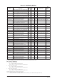
Annex 1 - Conforming Products LVD ATEX Cat1/Cat2 ATEX Cert No. Cat2 ATEX Cert No.
CONTENTS 1 2 3 4 5 6 7 8 9 OVERVIEW. . . . . . . . . . . . . . . . . . . . . . . . . . . . . . . . . . . . . . . . . . . . . . . . . . . . . . . . . . 1 DESCRIPTION. . . . . . . . . . . . . . . . . . . . . . . . . . . . . . . . . . . . . . . . . . . . . . . . . . . . . . . . 2 2.1 General . . . . . . . . . . . . . . . . . . . . . . . . . . . . . . . . . .
GENERAL SAFETY INFORMATION Safety instructions for installation and operating personnel The operating instructions provided here contain essential safety instructions for installation personnel and those engaged in the operation, maintenance and servicing of the equipment. WARNING! Failure to comply with these instructions can endanger the lives or health of personnel and risk damage to the plant and the environment.
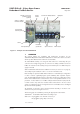
9387-FB-Px-R 5-Spur Open-Frame Redundant Fieldbus Barrier 9376-SP - trunk surge protection module (optional) Version number INM9380-RD-1 May 2012 9377-FB-R - fieldbus barriers Baseplate 9378-FT - fieldbus terminator module Trunk terminal assembly (TTA) Failover switch Carrier Trunk input/output Protective ground stud Spur connectors Alarm module Figure 1.
2 DESCRIPTION 2.1 General The assembly consists of a stainless steel baseplate, together with a trunk-wiring terminal assembly (TTA), two carrier-mounted fieldbus barriers and a fieldbus alarm module. Each barrier module can convert a single, non-intrinsically safe fieldbus trunk into six, galvanically isolated, intrinsically safe (IS) spur connections for connection to Foundation™ fieldbus H1 fieldbus instruments.
Consequently, if a spur ‘fail-over’ occurs, an alarm is signalled quickly to the host, via the fieldbus connection, to facilitate any necessary remedial action. The five remaining spurs are available to the user for connection to field devices. 2.3 Trunk Terminal Assembly The incoming trunk wiring is terminated inside a separate compartment, called the Trunk Terminal Assembly (TTA), that contains increased safety (Ex e) trunk wiring terminals.
c) An assembly has limited ingress protection and must be provided with protection appropriate to the environment in which it is located. The following table provides guidance on minimum environmental protection for specific locations.
After mounting the assembly Check that: • none of the component parts have suffered any damage, • the baseplate of the assembly is not distorted • the mounting bolts/nuts are all tightened as recommended above. 4 INITIAL ELECTRICAL INSTALLATION WARNING! Before starting any electrical installation work, ensure that the incoming trunk connection is isolated from any source of power. CAUTION Assembly temperatures could rise to 75°C.
4.2.2 Cable shield ground The cable shield is normally electrically isolated from the protective earth ground, although the two may be deliberately interconnected in some grounding arrangements. The cable shield wiring of both the trunk and spur cables should be connected to the local terminals marked with an ‘S’. WARNING! The following may involve changes to wiring in the Trunk Terminal Assembly.
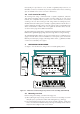
Nonintrinsically safe trunk T 9387-FB-R 5-spur, open frame assembly Host Control System T 9377-FB-R Fieldbus Barrier module (5/6-spur) Fieldbus Power Supply 9377-FB-R Fieldbus Barrier module (5/6-spur) 6 Intrinsically safe spur Alarm module 1 2 3 4 5 Fieldbus instruments Nonintrinsically safe trunk T 9387-FB-R 5-spur, open frame assembly Host Control System Fieldbus Power Supply 9377-FB-R Fieldbus Barrier module (5/6-spur) 9377-FB-R Fieldbus Barrier module (5/6-spur) 6 Intrinsically s
With this arrangement, the fieldbus trunk shield is separated from the spur cable shields. It should be adopted if plant or local regulations require that the spur cable shields be grounded at the Fieldbus Barrier. For this arrangement, connect the carrier shield ground wire (marked A) into Terminal 3. Note: After configuring the required grounding option, tighten all screw terminals to a recommended torque of 0.6 Nm. 4.2.
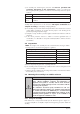
Position of Trunk Surge module (optional) Position of Trunk Terminator module (if required) Cover retaining screw Trunk wiring terminals Slide protective cover in this direction to remove Carrier Trunk cable entry area Protective ground stud Baseplate edge Trunk cable grommets Figure 4.4 - Trunk Termination Assembly (TTA) Spare Active Overall shield Trunk in (with Active + Spare cable pairs) Figure 4.
b) The trunk cable(s), which will be free of any armouring and presented as a shielded pair, should be fed through the supplied grommet, which should have been cut cleanly with a sharp knife to ensure that the IP30 rating for the TTA will be maintained. c) Cable ferrules must be fitted to any stranded cable or screen wiring that is being used d) Connect the prepared ends of the fieldbus trunk cable(s) into the appropriate ‘+’ , ‘–‘ and ‘S’ terminals, shown in Figure 4.
4.6.2 Fitting FS32 spur surge-protection modules FS32 modules are pluggable surge-protection units that integrate easily with the standard pluggable connector and which direct excessive spur surge currents to the protective local ground. Figure 4.7 - FS32 spur surge-protection module fitted on spur connector To fit an FS32: 1. Unscrew the two captive screws securing the standard pluggable connector (supplied on the carrier) and remove it from its socket. 2.
5 MAINTENANCE When the enclosure is installed in a hazardous area it is important for personnel to understand what activities are permissible when fieldbus power is present and what are not. WARNING! Read and understand what work is permitted on the equipment. Failure to comply with these instructions can endanger the lives or health of personnel and risk damage to the plant and the environment. 5.
a) Engage the locating guides (A) of the 9377-FB-R Fieldbus Barrier module into the sockets provided on the carrier and push the module fully into place. b) Tighten the three captive fixing screws (C & D) to a recommended torque of 0.9Nm to secure it. C D Fail-over button A B C A B Figure 5.1 - Fieldbus Barrier module – fitting & removal 5.2.
4. To restore Barrier A to the “active” mode, press the B>A fail-over button located beside Barrier B. Control of all spurs now returns to Barrier A while Barrier B goes into “standby” mode. * NOTE Operating the fail-over buttons will not allow active spurs to be transfered to a missing or failed barrier module. Terminator and Trunk Surge Protection modules Figure 5.
5.2.3.1 Mounting a module Refer to Figure 5.4. Orientate the module so that the smaller front clip is facing the user, then: • lower the module so that the safety retaining clip on the TTA housing fits into the loop on the module • locate the terminal pins into their contact sockets on the TTA housing and • push the module home until front and rear retaining clips engage. 5.2.3.2 Removing a module Refer to Figures 5.3 and 5.4 for further information.
5.4 Trunk connections WARNING! No part of the Trunk Terminal Assembly may be worked while the assembly is powered, unless the environment is known to be non-hazardous. Before any work starts on the Trunk Terminal Assembly the trunk power to the enclosure must be isolated, or a gas clearance certificate obtained. Once the conditions are known to be safe, the protective plastic cover of the Trunk Terminal Assembly (TTA) may be removed.
6 TROUBLESHOOTING The Redundant Fieldbus Barriers are fitted with LED indicators to assist the user in fault identification. Consult the following tables to understand the meaning of the LED states. Power LED (Green) ON OFF Trunk power applied Insufficient or no trunk power NOTE The Power LED will not light until the voltage at the barrier has risen to a value of at least 15.7V, but could remain lit even after the voltage has dropped to around 13.0V.
7 ALARM MODULE - OPERATION & CONFIGURATION 7.1 Introduction As with all redundant systems, early notification of the failure of a system component is important so that the fault can be rectified before a second fault is allowed to occur. A second fault is likely to interrupt the process, so restoring redundant operation is vital in maintaining high levels of system availability.
7.2.1 DI Function Blocks: failure alarm status of 9377-FB-R barrier modules The two discrete input blocks conform to FF standard FF891 and are used by the TTH300 for cyclic reading out of extended diagnostics information.
NOTE It is permitted for the alarm module to be removed or installed while the enclosure is powered because all its connections are rated “intrinsically safe”. 7.3.1 To remove the alarm module: 1. Loosen the two captive securing screws on the blue (spur) connector and extract the connector - repeat for the black (alarm) connector. 2. Loosen the two captive securing screws on the alarm module and lift it away from the circuit board complete with its wiring and connectors. 7.3.
8 ATEX INFORMATION The Essential Health and Safety Requirements (Annex II) of the EU Directive 94/9/ EC [the ATEX Directive - safety of apparatus] requires that the installation manual of all equipment used in hazardous areas shall contain certain information. This annex is included to ensure that this requirement is met. It compliments the information presented in this document and does not conflict with that information. It is only relevant to those locations where the ATEX directives are applicable.
8.3 Inspection and maintenance a) Inspection and maintenance should be carried out in accordance with European, national and local regulations which may refer to the IEC standard IEC 60079-17. In addition specific industries or end users may have specific requirements which should also be met. b) Care should be taken to limit dust accumulation on the exterior of the apparatus to a depth not exceeding 5mm.
RED RED RED RED TRUNK TERMINAL ASSEMBLY 9384-T A-ST 9384-T A-CC S TRUNK CONNECTIONS S 1– 2– NC S 1S 2S 3S OPTIONAL PE S LOCAL EARTH S SPUR SURGE OPTIONAL S S S S S S SPUR CONNECTIONS S 9382-CA-XX CARRIER 6 SPURS 9377-FB-R REDUNDANT FIELDBUS BARRIER MODULE A NOTE: CABLE ‘A’ IS SHOWN IN FACTORY DEFAULT GROUNDING OPTION - I.E.
This page left blank intentionally 24 INM9380-RD-1 May 2012
This page left blank intentionally INM9380-RD-1 May 2012 25
MTL Instruments Pty Limited 205-209 Woodpark Road Smithfield, New South Wales 2164 Australia Cooper Crouse-Hinds Japan KK MT Building 3F 2-7-5 Shiba Daimon, Minato-ku Tokyo Japan 105-0012 Tel: + 61 1300 308 374 Fax: + 61 1300 308 463 E-mail: mtlsales@cooperindustries.com Tel: +81 (0)3 6430 3128 Fax: +81 (0)3 6430 3129 E-mail: info@cooperindustries.jp Cooper Electric (Shanghai) Co. Ltd.