
RK94S27F, RK94S30F Installation Manual

E 4
STANDARD INSTALLATION INSTRUCTIONS
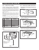
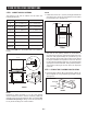
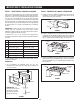
C. CABINET INSTALLATION: Avoid pinching the cord
between the oven and the wall. Adjust the position of the
oven so that the feet of the oven are tted into the holes
of the BOTTOM DUCT ASSEMBLY. See Figure 8.
DUCT RECESS
BOTTOM DUCT
ASSEMBLY
FOOT
FIGURE 8
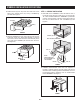
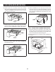
D. DISASSEMBLY: The FRONT FRAME and BACK FRAME
come pre-assembled with ball studs engaged in the
receivers. Separate the FRONT FRAME from the BACK
FRAME. Place the assembly facedown on a protected
surface. At the location of the ball stud, insert a athead
screwdriver between the FRONT FRAME and the BACK
FRAME and gently pry up to disengage the ball stud from
the receiver. Repeat for each corner. See Figure 9.
FIGURE 9
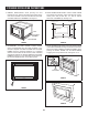
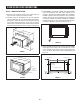
E. BACK FRAME INSTALLATION: Position BACK FRAME
equal space top to bottom, side to side. Mark for 4 holes,
center punch and pre-drill with
1
/16" drill bit. Secure
frame with 4 SCREWS (G). See Figure 10.
EQUAL GAP TOP, BOTTOM
EQUAL GAP
SIDE TO SIDE
MOUNTING HOLES
MOUNTING HOLES
MOUNTING HOLES
MOUNTING HOLES
FIGURE 10
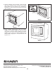
F. FRONT FRAME INSTALLATION: Place the FRONT FRAME
onto the BACK FRAME and align ball studs and receivers.
Secure the FRONT FRAME to the BACK FRAME by rmly
pushing the FRONT FRAME onto the BACK FRAME,
engaging the 4 snap attachments. See Figures 11-12.
SNAP
ATTACHMENT
FIGURE 11
FIGURE 12