
Instructions / Assembly


2
E
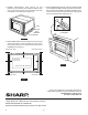
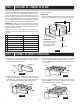
Provide an opening in the wall or cabinet as indicated in
Figure 1. The depth should be a minimum of 20-1/8". If the
Depth (E) dimension is greater than 21", the outlet location
may be in any area on the rear wall. The oor of the opening
should be constructed of plywood strong enough to support
the weight of the oven (approximately 100 lbs.) and should
be level for proper operation of the oven.
NOTE: While the proper function of the oven does not
require that the opening be enclosed (with sides, ceiling
and rear partition), this may be required by local code, and
it is suggested that the local code be checked for any such
requirement.
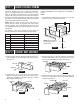
The opening in the wall or cabinet must be within the
following dimensions, centered horizontal to the cabinet.
RK-94S27 RK-94S30
A 20" 20"
B 26-7/8" 29-7/8"
C 18-1/2" 18-1/2"
D 25-1/4" 25-1/4"
E Min. 20-1/8" Min. 20-1/8"
F 5" 5"
G 10" 10"
A. Insert the edge of DUCT (B) into the hold lip of DUCT (C).
Secure together by using a SCREW (I) provided in the kit.
See Figure 2.
DUCT (C)
DUCT (B)
SCREW (I)
Figure 2
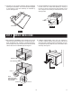
B. Position DUCT (A)-1 on the top of the oven inserting
edge of DUCT (BC) assembly into hole lip of DUCT (A)-1.
Tighten two SCREWS (I), securing DUCT (A)-1 to DUCT
(BC) assembly. See Figure 3.
SCREW (I)
DUCT (A)-1
DUCT (BC)
SCREW (I)
Figure 3
Outlet should NOT be in the shaded area as indicated on
Figure 1.
NOTE
• If the dimension of DEPTH (E) is more than 21", the outlet
location may be any area on the rear wall.
D
C
34-1/2” MIN.
FLOOR
FLOOR
A
B
G
F
E
STEP 1 CABINET OR WALL OPENING
STEP 2 EXHAUST DUCT ASSEMBLY
C. Position DUCT (A)-2 on the top of the oven and insert it
into the hold lip of DUCT (A)-1. Secure DUCT (A)-2 to DUCT
(A)-1 using two SCREWS (I) provided. See Figure 4.
SCREW (I)
SCREW (I)
DUCT (A)-2
DUCT (A)-1
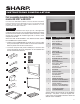
D. Position DUCT (A)-3 on top of the oven and insert it into
DUCT (A)-2. Secure DUCT (A)-3 using three SCREWS (I)
provided. See Figure 5.
SCREW (I)
SCREW (I)
SCREW (I)
DUCT (A)-3
DUCT (A)-2
NOTE: Floor of opening
should be 90˚ to front
cabinet frame.
Figure 1
Figure 4
Figure 5