
Service manual


1. PICTURE TUBE
Size : 17 inch
DefIection Angle : 90°
Neck Diameter : 29.1 mm
Stripe Pitch : 0.24 mm
Face Treatment : W-ARASC (Anti-Reflection and
Anti-Static Coating)
Internal : Anti-Glare
2. SIGNAL
2-1. Horizontal & Vertical Sync
1) Input Voltage Level : Low=0~1.2V, High=2.5~5.5V
2) Sync Polarity : Positive or Negative
2-2. Video Input Signal
1) Voltage Level : 0 ~ 0.7 Vp-p
a) Color 0, 0 : 0 Vp-p
b) Color 7, 0 : 0.467 Vp-p
c) Color 15, 0 : 0.7 Vp-p
2) Input Impedance : 75 Ω
3) Video Color : R, G, B Analog
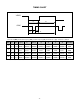
4) Signal Format : Refer to the Timing Chart
2-3. Signal Connector
3 row 15-pin Connector (Attached)
2-4. Scanning Frequency
Horizontal : 30 ~ 70 kHz
Vertical : 50 ~ 160 Hz
3. POWER SUPPLY
3-1. Power Range
AC 110~220V (Free Voltage), 60Hz, 2.0A Max.
3-2. Power Consumption
4. DISPLAY AREA
4-1. Active Video Area :
• Max Image Size - 325.4 x 244.1 mm (12.81" x 9.61")
• Preset Image Size - 310 x 230 mm (12.20" x 9.06")
4-2. Display Color : Full Colors
4-3. Display Resolution : 1280 x 1024 / 60Hz(Max)
(Non-Interlace)
4-4. Video Bandwidth : 110 MHz
5. ENVIRONMENT
5-1. Operating Temperature: 0°C ~ 40°C
(Ambient)
5-2. Relative Humidity : 10%~ 90%
(Non-condensing)
5-3. Altitude : 5,000 m
6. DIMENSIONS (with TILT/SWIVEL)
Width : 415 mm (16.34 inch)
Depth : 432 mm (17.00 inch)
Height : 413 mm (16.25 inch)
7. WEIGHT (with TILT/SWIVEL)
Net Weight : 17.0 kg (37.48 lbs.)
Gross Weight : 19.5 kg (42.99 lbs.)
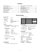
CONTENTS
- 2 -
SPECIFICATIONS ................................................... 2
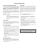
SAFETY PRECAUTIONS ........................................ 3
TIMING CHART ....................................................... 4
OPERATING INSTRUCTIONS ................................ 5
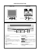
CONTROL LOCATION ............................................ 7
WIRING DIAGRAM ................................................. 8
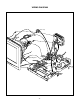
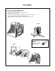
DISASSEMBLY ....................................................... 9
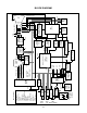
BLOCK DIAGRAM ................................................. 10
DESCRIPTION OF BLOCK DIAGRAM................... 11
ADJUSTMENT ...................................................... 13
TROUBLESHOOTING GUIDE .............................. 15
EXPLODED VIEW................................................... 25
REPLACEMENT PARTS LIST ............................... 27
PIN CONFIGURATION........................................... 33
SCHEMATIC DIAGRAM......................................... 38
PRINTED CIRCUIT BOARD................................... 40
SPECIFICATIONS
MODE
NORMAL (ON)
STAND-BY
SUSPEND
OFF
POWER CONSUMPTION
73 W
less than 15 W
less than 15 W
less than 5 W
LED COLOR
GREEN
AMBER
AMBER