
Specifications


Maxiva UAX
October 17, 2013
3‐35
888‐2693‐004 WARNING:Disconnectprimarypower priortoservicing.
Copyright©2013,HarrisBroadcast
FollowtheprocedurebelowtosaveanRTACCorrectionsetup.
STEP 1
Thetransmittershouldbeoperatingproperlyat100%power.
STEP 2 RefertoRTACSetupPage1onleftFigure3‐34onpage3‐33.SettheLinear
andNonline
arRTACcorrectionstoAdapt.
STEP 3 Afterashorttime,thenumberofsuccessesandattemptswillincrement
abovetheRTACLinearandNonlinearBypassselectionsoftkeys.Boththe
LinearandNonlinearcorrectorsshouldshowoneormoresuccessful
corrections.Verifythatthemeasuredperformanceofthesignalisadequate
usingappropriatetestequipment.LSBandUS
Bshouldersarefoundinthe
ExciterHomePerformancesubwindowFigure3‐28onpa
ge3‐28.These
parametersar
ediscussedinTable3‐19onpage3‐28,Performancesub
window.
STEP 4 AftertheRTACadaptationhasbeensuccessful,presstheRTACLinearand
NonlinearHoldsoftkeystoholdtheadaptiveprocesssteady.
Note
In the following step, the title of the selected set may be changed by clicking in the white box of the desired
set and entering a desired title.
STEP 5 ByselectingNextsoftkey ,gotoRTACSetupPage2showninFigure3‐34on
page3‐33.Selec
tacorrectionset,andpress‘Save’tostoretheRTACsetup.
3.7.4.3 OperateRTACfromaStoredFilterSet
TooperateRTACfromaStoredset,followtheprocedurebelow.
STEP 1
IntheStoredCorrectionSet ssubwindowoftheRTACSetupScreen2onright
Figure3‐34onpage3‐33,presstheSelectsoftkeytotheleftofthedesired
correctionset.ThatbuttonwillturnGreen.SelectPrevsoftkeytoreturnto
RTACPage1.
STEP 2 OntheRTACSetupPage1,onleftFigure3‐34onpage3‐33,setLinearand
NonlineartoSt
oredforoperationwiththeselectedstoredset.
STEP 3 Endofprocedure.
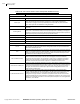
3.7.5 DUC/RTACSetupScreen3&4
Figure 3-35 LPU DUC/RTAC Setup Screens 3 & 4