
Specifications


Maxiva UAX
October 17, 2013
5‐17
888‐2693‐004 WARNING:Disconnectprimarypower priortoservicing.
Copyright©2013,HarrisBroadcast
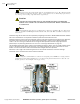
Figure 5-9 5 Station Example for Post-Filter RTAC Samples
Multiplexedco
mbiningsystemscanmakeitdifficultfortheindividualexciterstoprovideoptimaladaptivelinear
pre‐correctionduetointerferencefromothertransmittedsignalsthatarepresentonthecombinedpost‐filter
sample.Solutionsthatallowthelinearpre‐correctiontobeeffectivearecasedependentandvarydependingon
ch
annelsandpowerlevelsbeingcombined.
5.5.3.1 RTACSetupProcedureforCombinedChannelOperation
Theprocedurethatfollowsisconservativeandwillproducegoodresultsinmostcases.Ifthepoweroutputratio
betweencombinedtransmittersisextreme,additionalactionsmayberequired.
STEP 1
Connectsamplecablefrompost‐filterin‐linecouplertoN‐waysplitterand
attachsamplecablesfromsplittertoeachexciterRTACpost‐filtersample
port.Thecablesmustbehighqualityanddoubleshielded.Anyoutside
interferenceonthecableswillaffectRTACperformance.Thesignallevelinto
eachRT
ACpost‐filtersampleportshouldbeanominal‐5dBm(totalaverage
power,measuredwithpowermeter,allchannelsoperating)foroptimal
performance.
STEP 2 Connectpre‐filterRTACsamplestakenfromadirectionalcoupleratthe
outputofeachtransmittertotheRTACpre‐filterportoneachexciter.The
cablesmustbehighqualityanddoubleshielded.Anyoutsideinterference