
Installation Guide


3
INSTALLATION – 30” MODEL SDH3042DB
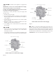
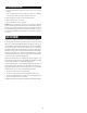
A. 30” (762 mm)
B. 21” (533 mm)
C. 5/32” (4 mm)
D. 2-5/32” (55 mm)
E. 29-5/8” (753 mm)
F. 19-7/8” (505 mm)
G. Minimum: 13/32” (10 mm)
Maximum: 25/32" (20mm)
H. Minimum: 2” (51 mm)
I. Minimum: 30” (762 mm)
J. Minimum: 2” (51 mm)
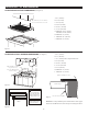
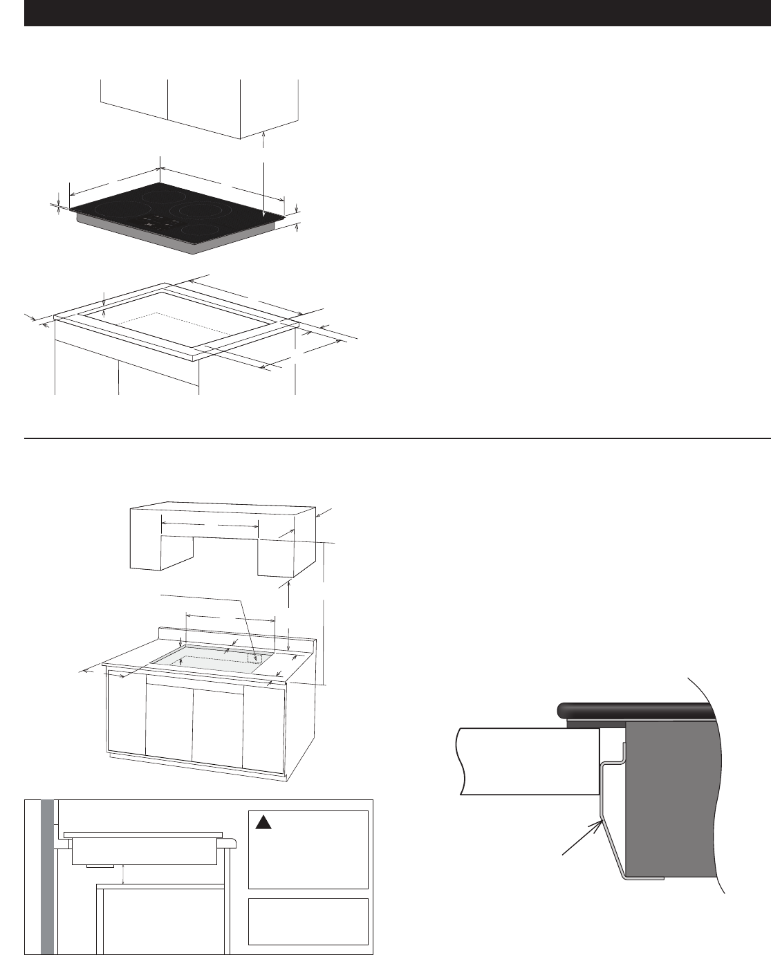
A. 30” (762 mm)
B. 13” (330 mm)
C. 30” (762 mm) min to unprotected wood
D. 18” (457 mm)
E. 29-5/8” (753 mm)
F. 19-7/8” (505 mm)
G. 4-1/2 (114mm)
H. Minimum: 2” (51 mm)
I. Minimum: 2” (51 mm)
Figure 3
Figure 4
Figure 5
Figure 6
COOKTOP AND CUTOUT DIMENSIONS (See Figure 3)
COOKTOP CUTOUT OPENING DIMENSIONS (See Figure 4)
I*
A
D
B
E
C
H
G
F
J
30” (76.2 cm) min. for cabinet
* Do not obstruct these areas.
A
B
D
E
G
F
C
H
I
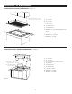
Approximate location
of junction box,
min. 12" (304.8 mm)
below cooktop
Countertop
Do not remove spacer
Spacer Graphic Profile
2-1/2” (63.5 mm)
OVEN
!
CAUTION
Note: do not put a
divider between the
oven and cooktop
It is very important to
keep 2-1/2” (63.5 mm)
distance between the
cooktop and the oven.
NOTE: The cooktops include spacers on both sides to ensure proper
airow once installed. Do not remove the spacers. See Figure 6 above.