GSM TELEPHONE SGH-T519 GSM TELEPHONE CONTENTS 1. Safety Precautions 2. General Introduction 3. Specification 4. Product Funtion 5. Circuit Description 6. Test Command & Test Procedure 7. Array course control 8. Exploded View and its Parts list 9. MAIN Electrical Parts List 10. Flow Chart of Troubleshooting and Circuit Diagrams 11. PCB Diagrams 12. Block Diagrams 13.
Contents 1. Safety Precautions 1-1. Repair Precaution ...........................................................................1-1 1-2. ESD(Electrostatically Sensitive Devices) Precaution ...........................1-2 2. General Introduction 3. Specification 3-1. GSM General Specification ..............................................................3-1 3-2. GSM TX Power class ......................................................................3-2 3-3. EDGE TX Poser Level ..............................
Contents 9. MAIM Electrical parts list 10. Flow Chart of Troubleshooting and Circuit Diagrams 10-1. Baseband 10-1-1. Power on ..............................................................................10-1 10-1-2. Initial ....................................................................................10-3 10-1-3. Sim Part ...............................................................................10-4 10-1-4. Charging Part ........................................................................
This Service Manual is a property of Samsung Electronics Co.,Ltd. Any unauthorized use of Manual can be punished under applicable International and/or domestic law. ⓒ Samsung Electronics Co.,Ltd. Code No.: GH68-12034A 2006. 08. Rev.1.
1. Safety Precautions 1-1. Repair Precaution ● Repair in Shield Box, during detailed tuning. Take specially care of tuning or test, because specipicty of cellular phone is sensitive for surrounding interference(RF noise). ● Be careful to use a kind of magnetic object or tool, because performance of parts is damaged by the influence of manetic force. ● Surely use a standard screwdriver when you disassemble this product, otherwise screw will be worn away. ● Use a thicken twisted wire when you measure level.
Safety Precautions 1-2. ESD(Electrostatically Sensitive Devices) Precaution Several semiconductor may be damaged easilly by static electricity. Such parts are called by ESD(Electrostatically Sensitive Devices), for example IC,BGA chip etc. Read Precaution below. You can prevent from ESD damage by static electricity. ● Remove static electricity remained your body before you touch semiconductor or parts with semiconductor.
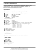
2. General Introduction The SGH-T519 Quad Band phone functions as digital phone working in GSM (Global System for Mobile communications)850,EGSM900, DCS1800 and PCS(PersonalCommunication System)1900 modes. ● ● ● ● ● ● ● ● Dimension Weight LCD R/F band Vocoder Antenna SIM BLUETOOTH : 113 x 50 x 8.6 mm (with Standard Battery) : 76g (with Standard Battery) : LCD 260K TFT Color LCD (176 x 220) 1.
3. Specification 3-1. GSM General Specification GSM850 EGSM900 DCS1800 PCS1900 F r e q . Ba n d [ M Hz ] Uplink/ Downlink 824~849 869~894 880~915 925~960 1710~1785 1805~1880 1850~1910 1930~1990 A RFCN rang e 128~251 0~124& 975~1023 512~885 512~810 T x /Rx s pacing 45 MHz 45 MHz 95 MHz 80 M Hz GP RS 270.833 Kb ps 3. 692 us 270.833 Kb ps 3. 692 us 270.833 Kb ps 3. 692 us 270.833 Kbp s 3.692 us EDGE 812.5 K b ps 3. 692 us 812.5 K b ps 3. 692 us 812.5 K b ps 3. 692 us 812.5 K bp s 3.
Specification 3-2.
Specification 3-3.
4. Product Function Main Function -1.3 Megapixel Camera and Camcorder -Bluetooth® Wireless Technology -Instant Messageing capability -Multimedia capability -Fun & Apps featureprovides My Files, music player, games, alarms, calendar, task list, calculator, world time, unit conversion, timer, and stopwatch.
5. Circuit Description < RF Circuit Description of SGH-T519 > 1. FEM (F100) ==> Switching Tx, Rx path for GSM850, EGSM900, DCS1800 and PCS1900 controlled by logic. Integration of GSM850, EGSM900, DCS1800 and PCS1900 RX SAW Filters. To convert Electromagnetic Field Wave to Acoustic Wave and the pass the specific frequency band.
Circuit Description - TX Function The device implements Skyworks Polar Loop transmit architecture. This architecture autonomously splits the amplitude and phase within the device using the traditional analog In-Phase and Quadrature (I/Q) signals. The filter-saving advantage of the translation-loop approach is embedded in the architecture. Also included is an AM loop that provides both signal AM and power level control.
Circuit Description ● Timing and control unit ● RF serial interface ● Low-power sleep mode controller ● Baseband Transmitter / Receiver ● Voice input and output 2. WM8955L(UCD401) ==> The WM8955L is a low power, high quality stereo DAC with intergrated headphone and loudspwaker amplifiers, designed to reduce external component requirements in portable digital audio application. The on-chip headsphone amplifiers can deliver 40mW into a 16Ω load.
Circuit Description ● Synchronous serial port supporting ● Programmable 48-bit general-purpose IO unit, keyboard interface, programmable interval timer and real-time clock. ● SD/MMC controller that supports interfacing to secure digital/multimedia memory card. Two DSP16000 dual-MAC DSP cores;● Up to 404 million MACs per second at 101 MHz. ● Memory complement; - DSP0 : 144K X 16-bit ROM, 40k X 16-bit RAM. - DSP1 : 96K X 16-bit ROM, 16k X 16-bit RAM.
6. Test Command & Test Procedure 6-1. Calibration Equipment - HP 8960 DC Power Supply Test Jig Configuration HP8960 RF DC POWER SUPPLY GPIB + + -- PC TEST JIG GPIB Serial Serial 6-2.
Test Command & Test Procedure 6-3. Tx Power Tune up Procedure - GMSK 1) Procedure: a. Calibraion equipment HP8960 and the cell phone are connected through RF cable. b. Target power ( required power level according to the specification which should be set by calibration program) is set to equipment as power level (ex: GSM 5 level is 32.5 dBm). c. Activate phone in Tx_Mode_Only. d.
Test Command & Test Procedure - 8PSK 1) Procedure: a. Calibraion equipment HP8960 and the cell phone are connected through RF cable. b. Target power ( required power level according to the specification which should be set by calibration program) is set to equipment as power level (ex: GSM 8 level is 27 dBm). c. Activate phone in Cont_8psk_Tx_Mode_Only. d. HP8960 equipment measures transmitted power through rf test cable from the phone and reports measured level to calibration program. e.
Test Command & Test Procedure See the TX power level definition table below.
7.
Array course control Software Downloading 7-1. Downloading Binary Files • Two binary files for downloading T519. – T519XXYY.s3 : Main source code binary. 7-2. Pre-requsite for Downloading • Downloader Program(OptiFlash.
Array course control 7-3. S/W Downloader Program 1. Load the binary download program by executing the “OptiFlash.exe” 2. Select the “Options” -> “Settings” -> “Generic” -> “Specify hardware platform”. Choose hardware platform for the downloader file setting.
Array course control 3. Select the COM port when the download cable is connected Up to 64 ports are supported. Additionally you can select the maximum transfer speed OptiFlash will use to communicate with the phone. However, OptiFlash will use a slower speed if either the PC’s or the phone’s serial hardware is incapable of handling the selected speed.
Array course control 4. Select the“Flash&Verify” -> “Browse” Set the directory path and choose the latest s/w binary, for example “T519XXYY.s3”, for the downloader binary setting. In case of D407 the reserved regions are not a necessity. (It is defined in platform.
Array course control 5. Click “OK” button then press “Flash”. (Before pressing ‘Flash’ button, push the button ‘*’and ‘END’ at the same time. Then press ‘Flash’.) Downloader will upload the binary file as below for the downloading. 6. When downloading is finished successfully, there is a “All is well” message. 7. After finishing downloading, Certain memory resets should be done to guarantee the normal performance. 8. Confirm the downloaded version name and etc.
8. Exploded View and its Partslist 8-1.
Exploded view and its Part list 8-2.
Exploded view and its Part list CBF INTERFACE-DATA LINK CABLE GH39-00514A CHARGER-SGHD820 TA (LTA) GH44-01174A UNIT-EARPHONE(BLK) GH59-02499A MPR-VINYL BOHO T MAIN WINDOW GH74-26613B AS-LCD WINDOW TAPE GH81-05218A AS-LCD WINDOW GH81-05937A RMO-RUBBER LCD CONN GH73-07778A RMO-RUBBER EAR JACK GH73-07780A RMO-RUBBER BGA GH73-07922A RMO-RUBBER CSP GH73-08343A MPR-TAPE CAMERA KEY GH74-25950A MPR-TAPE VOLUME KEY GH74-25951A MPR-SPONGE BT GH74-26377A MPR-TAPE, 3X3XT3.
Disassembly and Assembly instructions 8-3. Disassembly 1 2 1.Unscrew 4 points of a rear. 1.Disjoint a top of the rear with a tool. ※ caution ※ caution 1.Be careful not to do damage and scratch the phone. 1.Be careful not to do damage and scratch the phone. 3 4 1.Remove both side keys,then detach the EL KEY FPCB CONNECTOR. 1.Lift up a board carefully and detach a PBA. 1.Be careful not to cut both side keys and damage to camera connector pins 1.
Disassembly and Assembly instructions 7 1. Detach a LCD from LCD braket. ※ caution 1.Be careful not to do damage and scratch the phone.
Disassembly and Assembly instructions 8-4. Assembly 1 2 1. Attach an EL sheet 2. Attach a key pad 2. Press a camera window. 1. Attach a rear deco. and camera window A. B. C. D. E. Remove a adhesive tape of EL sheet. Attach a EL sheet Attach a mic cover Attach a key pad Press a key pad 2 - Pressure kgf : 6 ± 1 kgf/cm A. Examine the surface of rear,and attach a rear deco. and camera window. B. Press a camera window. 2 - Pressure kgf : 6 ± 1 kgf/cm 3 1. Attach a SPK_MOT FPCB 2.
Disassembly and Assembly instructions 4 1. Examnine the surface of 2. Place LCD and sponge CARRIER LOWER CAMERA SPONGE LCD place hole SHORT PREVENTION TAPE Baseline ABSORBER Attach keeping away from soldering part. completion A.Place a LCD inserting LCD connector on the front of CARRIER LOWER. B.Place a LCD into place hole of CARRIER LOWER correctly. C.Press carefully the top (SAMSUNG logo) and bottom( T-Mobile logo) of LCD . D.
Disassembly and Assembly instructions 6 1. Place a PBA Press the connector horizontally to a PBA A. Press carefully the top of PBA with your right hand grasping CARRIER LOWER with your left hand. B. Press both sides of PBA until it clicks into the CARRIER LOWER. (Grasp the edge of LCD during work) C. Press the LCD connector to the CARRIER LOWER horizontally. 7 1. Place the intenna A.Press the intenna until it clicks into the PBA B.Put the SPK CONNECTER horizontally C.
Disassembly and Assembly instructions 8 1. Solder the intenna 2. Place the camera A. Solder the intenna with soldering jig B. Place the camera into a groove of CARRIER LOWER. C. Press carefully after placing camera module. 9 1.Place the PBA side keys A. Place the PBA on the FRONT. B. Remove the camera protection film. C. Place side keys into place.
Disassembly and Assembly instructions 10 1. Remove the protection film inside 3. SCREW CAMERA WINDOW 2. Place the REAR Locker No.1 Locker No.2 A. Place the top of a REAR and press down until it clicks into the Front B.Press the Locker No.1 and Locker No.2 C.SCREW.
9.
Electrical Parts List SEC CODE Design LOC Discription 1203-003737 Q401 IC-POSI.FIXED REG. SA 1203-003737 Q402 IC-POSI.FIXED REG. SA 1203-003737 U405 IC-POSI.FIXED REG. SA 1203-003767 Q400 IC-POSI.FIXED REG. SA 1203-003787 Q403 IC-POSI.FIXED REG.
Electrical Parts List SEC CODE Design LOC Discription 2007-000157 R428 R-CHIP SA 2007-000157 R429 R-CHIP SA 2007-000171 R105 R-CHIP SA 2007-000171 R106 R-CHIP SA 2007-000171 R114 R-CHIP SA 2007-000171 R135 R-CHIP SA 2007-000171 R136 R-CHIP SA 2007-000171 R225 R-CHIP SA 2007-000171 R227 R-CHIP SA 2007-000171 R305 R-CHIP SA 2007-000171 R410 R-CHIP SA 2007-000171 R411 R-CHIP SA 2007-000171 R452 R-CHIP SA 2007-000171 R453 R-CHIP SA 2007-000172 R213 R
Electrical Parts List SEC CODE Design LOC Discription 2007-007316 R304 R-CHIP SA 2007-007317 R104 R-CHIP SA 2007-007468 R403 R-CHIP SA 2007-007468 R409 R-CHIP SA 2007-007489 R316 R-CHIP SA 2007-007590 R310 R-CHIP SA 2007-007741 R109 R-CHIP SA 2007-007741 R217 R-CHIP SA 2007-007741 R401 R-CHIP SA 2007-007741 R408 R-CHIP SA 2007-007741 R420 R-CHIP SA 2007-007741 R423 R-CHIP SA 2007-007798 R215 R-CHIP SA 2007-008045 R115 R-CHIP SA 2007-008045 R125 R
Electrical Parts List SEC CODE Design LOC Discription 2007-008483 R312 R-CHIP SA 2007-008483 R314 R-CHIP SA 2007-008483 R317 R-CHIP SA 2007-008483 R404 R-CHIP SA 2007-008486 R235 R-CHIP SA 2007-008516 R120 R-CHIP SA 2007-008531 R116 R-CHIP SA 2007-008531 R419 R-CHIP SA 2007-008542 R112 R-CHIP SA 2007-008542 R124 R-CHIP SA 2007-008542 R127 R-CHIP SA 2007-008542 R130 R-CHIP SA 2007-008542 R318 R-CHIP SA 2007-008542 R450 R-CHIP SA 2007-008542 R451 R
Electrical Parts List SEC CODE Design LOC Discription 2203-000254 C213 C-CER,CHIP SA 2203-000254 C214 C-CER,CHIP SA 2203-000254 C216 C-CER,CHIP SA 2203-000254 C217 C-CER,CHIP SA 2203-000254 C232 C-CER,CHIP SA 2203-000254 C233 C-CER,CHIP SA 2203-000254 C332 C-CER,CHIP SA 2203-000311 C128 C-CER,CHIP SA 2203-000330 C102 C-CER,CHIP SA 2203-000330 C222 C-CER,CHIP SA 2203-000330 C223 C-CER,CHIP SA 2203-000438 C447 C-CER,CHIP SA 2203-000438 C450 C-CER,CHIP SA
Electrical Parts List SEC CODE Design LOC Discription 2203-005061 C451 C-CER,CHIP SA 2203-005061 C453 C-CER,CHIP SA 2203-005481 C405 C-CER,CHIP SA 2203-005481 C413 C-CER,CHIP SA 2203-005482 C206 C-CER,CHIP SA 2203-005482 C207 C-CER,CHIP SA 2203-005482 C221 C-CER,CHIP SA 2203-005482 C224 C-CER,CHIP SA 2203-005482 C225 C-CER,CHIP SA 2203-005482 C228 C-CER,CHIP SA 2203-005482 C230 C-CER,CHIP SA 2203-005482 C231 C-CER,CHIP SA 2203-005482 C302 C-CER,CHIP SA
Electrical Parts List SEC CODE Design LOC Discription 2203-006121 C306 C-CER,CHIP SA 2203-006137 C212 C-CER,CHIP SA 2203-006137 C333 C-CER,CHIP SA 2203-006137 C334 C-CER,CHIP SA 2203-006137 C404 C-CER,CHIP SA 2203-006194 C109 C-CER,CHIP SA 2203-006194 C129 C-CER,CHIP SA 2203-006194 C134 C-CER,CHIP SA 2203-006194 C135 C-CER,CHIP SA 2203-006194 C408 C-CER,CHIP SA 2203-006257 C219 C-CER,CHIP SA 2203-006257 C339 C-CER,CHIP SA 2203-006260 C205 C-CER,CHIP SA
Electrical Parts List SEC CODE Design LOC Discription 2203-006423 C301 C-CER,CHIP SA 2203-006423 C307 C-CER,CHIP SA 2203-006423 C340 C-CER,CHIP SA 2203-006423 C421 C-CER,CHIP SA 2203-006423 C424 C-CER,CHIP SA 2203-006466 C409 C-CER,CHIP SA 2203-006562 C130 C-CER,CHIP SA 2203-006562 C132 C-CER,CHIP SA 2203-006562 C229 C-CER,CHIP SA 2203-006562 C313 C-CER,CHIP SA 2203-006562 C316 C-CER,CHIP SA 2203-006562 C318 C-CER,CHIP SA 2203-006562 C319 C-CER,CHIP SA
Electrical Parts List SEC CODE Design LOC Discription 2203-006824 C435 C-CER,CHIP SA 2203-006824 C441 C-CER,CHIP SA 2203-006824 C442 C-CER,CHIP SA 2203-006825 C343 C-CER,CHIP SA 2203-006825 C345 C-CER,CHIP SA 2203-006838 C202 C-CER,CHIP SA 2203-006846 C106 C-CER,CHIP SA 2404-001348 C457 C-TA,CHIP SA 2404-001348 C458 C-TA,CHIP SA 2404-001352 C403 C-TA,CHIP SA 2404-001352 C459 C-TA,CHIP SA 2404-001352 C460 C-TA,CHIP SA 2404-001381 C414 C-TA,CHIP SA 2404-
Electrical Parts List SEC CODE Design LOC 2809-001293 TCX101 2901-001377 Discription STATUS OSCILLATOR-VCTCXO SA F301 FILTER-EMI SMD SA 2901-001377 F302 FILTER-EMI SMD SA 2901-001377 F303 FILTER-EMI SMD SA 2901-001377 F304 FILTER-EMI SMD SA 2911-000051 F100 DUPLEXER-FEM SA 3301-001158 L405 BEAD-SMD SA 3301-001158 L406 BEAD-SMD SA 3301-001208 L112 BEAD-SMD SA 3301-001534 F401 BEAD-SMD SA 3301-001659 L404 BEAD-SMD SA 3705-001421 RFS101 CONNECTOR-COAXIAL SA
10. Flow Chart of Troubleshooting 10-1.Baseband 10-1-1. Power ON 'Power ON' Does not work Check the current consumption Current consumption NO Download again ≥100mA ? YES Check the V bat. voltage NO Voltage ≥ 3.3V ? Charge the Battery YES Check the pins of UCD301 ① NO C316 ≥ 1.8V ? Check UCD301 and C316 YES C318 and C315 = 2.8V? NO YES NO C312=1.
Flow Chart of Troubleshooting VCCA_2.9V VCCD_2.9V VBAT VCCD_1.8V VCCD_2.9V C300 C301 C303 C302 C304 EAR_CHECK B4 C4 P13 L 11 F6 A6 M10 N11 P6 R2 K4 G5 J4 N5 N6 M3 J3 F11 K15 B15 E8 B13 C10 SIMCLK SIMRST SIMDATA VSIM VCCD_1.8V_EN VCCB_2.9V VCCA_2.9V VRF_2.9V VCCD_2.9V R300 DCS_TX_EN GSM_TX_EN BAT300 VBAT C312 UP_CS UP_SCLK UP_SDO UP_SDI E14 E13 E11 F12 D14 C316 C317 C313 C314 C315 C318 C321 C319 VCCB_2.
Flow Chart of Troubleshooting 10-3 SAMSUNG Proprietary-Contents may change without notice This Document can not be used without Samsung's authorization
Flow Chart of Troubleshooting 10-1-2. Initial Initial Failure NO The voltage at the C316=1.8V? The voltage at the C315=2.8V? Check the UCD301 (If it has some problem, it has to be replaced.) YES NO The voltage at the C216 " Low --> High" ? Check the UCD301 (If it has some problem, it has to be replaced.) YES ① NO There is 32.768KHz wave form at the C222, C223 ? Check the UCP201 YES The voltage is 2.
Flow Chart of Troubleshooting VCCD_1.6V VCCD_1.8V VRTC_1.5V VCCD_1.
Flow Chart of Troubleshooting 10-1-3. Sim Part "Insert SIM" is displayed on the LCD NO The voltage is 2.
Flow Chart of Troubleshooting ZD302 4 5 6 CH3 CH2 CH4 3 VN CH5 2 CH1 1 SIM301 VSIM SIM_RST SIM_CLK C306 C307 C308 C309 1 2 3 1 2 3 7 8 9 7 8 9 6 6 5 5 4 4 12 12 11 11 10 10 G G G G 16 15 14 13 SIM_IO C305 10-7 SAMSUNG Proprietary-Contents may change without notice This Document can not be used without Samsung's authorization
Flow Chart of Troubleshooting 10-1-4. LCD Display part LCD display is abnormal Check LCD connection and replace LCD LCD Backlight is on? NO pin#14 of HDC302 YES Check LCD Check HDC302 is high? NO YES pin#7 of U404 YES is high? NO ① NO C218 > 3.5V? Check C218 Recharge Bat. YES pin#6 of U404 NO is high? ② YES CHeck U404 C338, C340 is 2.
Flow Chart of Troubleshooting VCCD_2.9V VCCD_2.9V 1 6 2 5 3 4 ZD304 R320 1 3 5 7 9 11 13 15 17 19 21 23 25 27 1 3 5 7 9 11 13 15 17 19 21 23 25 27 29 29 LCD_DATA(13) LCD_DATA(14) LCD_DATA(15) 31 32 NC NC LCD_DATA(12) LCD_DATA(11) LCD_DATA(10) LCD_DATA(9) LCD_DATA(8) LCD_DATA(7) LCD_DATA(6) LCD_DATA(5) C338 2 4 6 8 10 12 14 16 18 20 22 24 26 28 30 2 4 6 8 10 12 14 16 18 20 22 24 26 28 30 LCD_DATA(4) LCD_DATA(3) LCD_DATA(2) LCD_DATA(1) LCD_DATA(0) LED+_13.
Flow Chart of Troubleshooting F304 F303 5 OUT1 IN1 1 LCD_D(9) LCD_DATA(10) 6 OUT2 IN2 2 LCD_D(10) LCD_D(7) LCD_DATA(11) 7 OUT3 IN3 3 LCD_D(11) LCD_D(8) LCD_DATA(12) 8 OUT4 IN4 4 GNDGND LCD_D(12) LCD_DATA(5) 5 OUT1 IN1 1 LCD_D(5) LCD_DATA(9) LCD_DATA(6) 6 OUT2 IN2 2 LCD_D(6) LCD_DATA(7) 7 OUT3 IN3 3 LCD_DATA(8) 8 OUT4 IN4 4 GND GND 9 10 9 10 F301 F302 LCD_DATA(15) 5 OUT1 IN1 1 LCD_DATA(14) 6 OUT2 IN2 2 LCD_DATA(13) 7 OUT3 IN3 3 LCD_D(4) LCD_DATA(4) 8 OUT4 IN4 4 GN
Flow Chart of Troubleshooting 10-1-5. Microphone Part Micro-phone does not work ① NO Is the connection status of HDC300 O.K? Reconnect connector of HDC300 YES Check the DC bias voltage on Mic path. ② NO The voltage of C406 is about 2.
Flow Chart of Troubleshooting 20 18 16 14 12 12 10 10 8 8 6 6 4 4 2 2 MIC+ 19 17 15 13 11 9 7 5 3 1 PWR_ON KEY_ROW(0) KEY_ROW(1) KEY_ROW(2) KEY_ROW(3) KEY_ROW(4) 19 17 15 13 11 9 7 5 3 1 MIC- ZD310 C310 C311 V306 V307 V311 V309 V310 10-12 SAMSUNG Proprietary-Contents may change without notice This Document can not be used without Samsung's authorization ZD311 20 18 16 14 V312 EL_PWR EL_PWR KEY_COL(0) KEY_COL(1) KEY_COL(2) KEY_COL(3) KEY_COL(4) NC 22 NC 21 HDC300
Flow Chart of Troubleshooting 10-1-6. Speaker Part There is no sound from speaker NO Is the connector HDC401 O.K? ① Reconnect HDC401 YES yes Are there any signal at L405, L406? Check & Replace L402, L403, HDC401 NO NO Are there any signal at R437, R438? NO R442 is high? YES NO The voltage at L404 >3.
Flow Chart of Troubleshooting VRF_2.9V U101 13M_BUF 1 NC VCC 6 2 A NC 5 3 GND R124 Y4 R123 R125 C137 R126 C133 CLK13M_TR C136 CLK13M_MC CLK13M_WM C140 VCCD_1.8V_EN VBAT VCCD_1.
Flow Chart of Troubleshooting 10-15 SAMSUNG Proprietary-Contents may change without notice This Document can not be used without Samsung's authorization
Flow Chart of Troubleshooting 10-1-7. Receiver Part There is no sound from receiver.
Flow Chart of Troubleshooting 10-17 SAMSUNG Proprietary-Contents may change without notice This Document can not be used without Samsung's authorization
Flow Chart of Troubleshooting 10-1-8. Camera part Camera function does not work ① NO Is the connect HDC301 ok? YES Connect the HDC301 ② NO C452 IS HIGH? Check U400 YES Pin #3 of Q400 = 1.5V? ③ NO YES Pin #1 of Q400 IS HIGH? Check Q400 NO YES Check Bat. ④ Pin #3 of Q403 = 2.8V? NO NO Pin #1 of Q403 = High? YES Q401 Check Bat.
Flow Chart of Troubleshooting VCAMIO_2.8V VCAM_1.5V VCAMA_2.
Flow Chart of Troubleshooting 10-20 SAMSUNG Proprietary-Contents may change without notice This Document can not be used without Samsung's authorization
Flow Chart of Troubleshooting 10-1-9. Mp3 part There is no MP3 sound from Earphone Are there any signal at the pin #5,7 of IFC400? YES Replace the Earphone NO ① YES Are there any signal at R410, R411? Check & Replace ZD403 NO ② YES Are there any signal at the pin #10,13 of UCD401? Check & Replace C457, C458 NO ③ YES Are there any signal at the C407, 417? Check C416, 417 NO Are there any signal at the PIN #5,6,7? ⑤ YES NO C445 & C446 =1.
PCM_FSYNC PCM_FCLK PCM_TXD CLK13M_WM R440 C454 C445 C422 R441 R439 C446 VCCD_1.8V C420 C424 VCCD_1.8V C419 A(1) A(2) CP_WEN CP_OEN MV3020_CS MV3020_INT C416 D(15) D(14) D(13) D(12) D(11) D(10) D(9) D(8) D(7) D(6) D(5) D(4) D(3) D(2) D(1) D(0) R447 R433 WM_CSB WM_SDIN WM_SCLK C421 VCCD_2.
Flow Chart of Troubleshooting 10-23 SAMSUNG Proprietary-Contents may change without notice This Document can not be used without Samsung's authorization
Flow Chart of Troubleshooting 10-24 SAMSUNG Proprietary-Contents may change without notice This Document can not be used without Samsung's authorization
Flow Chart of Troubleshooting 10-2. RF 10-2-1. GSM900 RX Continuous RX ON RF Input : 62 CH AMP : -50dBm ① NO NORMAL CONDITION Catch the channel ? Check soldered status of L103, C101, C104, L101 YES ② NO F100 Check Pin #17 ≥ -65dBm ? RFS101, C100 Resolder or Change YES ③ NO F100 Check Pin #5,6 ≥ -65dBm ? F100 Resolder or Change YES NO UCD100 Check Pin#6,7 ≥ -65dBm ? ④ Check soldered status of L108, L109, C121 YES NO UCD100 Check Pin#27 =1.
Flow Chart of Troubleshooting 10-26 SAMSUNG Proprietary-Contents may change without notice This Document can not be used without Samsung's authorization
Flow Chart of Troubleshooting 10-2-2. GSM1800 RX Continuous RX ON RF Input : 62 CH AMP : -50dBm ① NO NORMAL CONDITION Catch the channel ? Check soldered status of L103, C101, C104, L101 YES ② NO F100 Check Pin #17 ≥ -65dBm ? RFS101, C100 Resolder or Change YES ③ NO F100 Check Pin #3,4 ≥ -65dBm ? F100 Resolder or Change YES NO UCD100 Check Pin#8,9 ≥ -65dBm ? ④ Check soldered status of R135, R136, L106 YES NO UCD100 Check Pin#27 =1.8V ? CHECK UCD301 YES ⑤ UCD100 Check Pin#34 =Clean 2.
Flow Chart of Troubleshooting 10-2-3. GSM1900 RX Continuous RX ON RF Input : 62 CH AMP : -50dBm ① NO NORMAL CONDITION Catch the channel ? Check soldered status of L103, C101, C104, L101 YES ② NO F100 Check Pin #17 ≥ -65dBm ? RFS101, C100 Resolder or Change YES ③ NO F100 Check Pin #1,2 ≥ -65dBm ? F100 Resolder or Change YES NO UCD100 Check Pin#10,11 ≥-65dBm ? ④ Check soldered status of L110, L111, L107 YES NO UCD100 Check Pin#27 =1.8V ? CHECK UCD301 YES ⑤ UCD100 Check Pin#34 =Clean 2.
Flow Chart of Troubleshooting 10-2-4. GSM850 RX Continuous RX ON RF Input : 62 CH AMP : -50dBm ① NO NORMAL CONDITION Catch the channel ? Check soldered status of L103, C101, C104, L101 YES NO F100 Check Pin #17 ≥ -65dBm ? ② RFS101, C100 Resolder or Change YES ③ NO F100 Check Pin #7,8 ≥ -65dBm ? F100 Resolder or Change YES NO UCD100 Check Pin#4,5 ≥ -65dBm ? ④ Check soldered status of L104, L105, C120 YES NO UCD100 Check Pin#27 =1.8V ? CHECK UCD301 YES ⑤ UCD100 Check Pin#34 =Clean 2.
Flow Chart of Troubleshooting 10-2-5. GSM850 / GSM900 TX ① NO F100 Pin#17 About 2~3 dBm? NO F100 Pin#13 = High? UCD301 Check / Change YES YES RFS101, C100 Check / Change Level of F100 Pin#12 is 4~5dBm ? NO YES ② F100 Check & Change NO C108 = 3.7V? Check the Battery Block YES ③ NO Level of PAM101 Pin #6 is 1.
Flow Chart of Troubleshooting 10-31 SAMSUNG Proprietary-Contents may change without notice This Document can not be used without Samsung's authorization
Flow Chart of Troubleshooting 10-2-6. DCS1800 & PCS1900 TX ① NO F100 Pin#17 About 2~3 dBm? NO F100 Pin#11 = High? UCD301 Check / Change YES YES RFS101, C100 Check / Change Level of F100 Pin#10 is 4~5dBm ? NO YES ② F100 Check & Change NO C108 = 3.7V? Check the Battery Block YES ③ NO Level of PAM101 Pin #6 is 1.
AFC SAT_DET GSM74137_OUT VPC BAND_SEL DCS74137_OUT PAC_EN C134 R120 2 1 C107 GND OUT VCON VCC TCX101 R128 R104 R118 R127 3 4 R116 C135 VRF_2.9V R107 L115 C129 R112 C111 R115 C102 C109 CLK26M_RF C108 C110 GND 9 GND 17 GND 10 8 RSVD GND 11 GSM_OUT 12 GND 13 DCS|PCS_OUT 14 7 GSMIN 6 VPC 13M_BUF R108 3 BS 5 VBATT 4 VSUP GND 15 COUP_OUT 16 PAM101 2 DCS|PCS_IN 1 ENA Y4 NC 5 VCC 6 R126 3 GND 2 A 1 NC U101 C137 VRF_2.
11.
PCB Diagrams TP301 Q402 Q400 F401 U 401 ZD401 ZD407 Q403 D401 ZD408 U 400 ZD400 CN201 OSC401 O SC 2 0 1 UME201 UCP201 TP216 TP215 Q401 UCD301 UCD401 ZD305 F301 H D C 30 2 ZD301 MOD100 ZD304 Q100 U301 U 305 BTC400 ZD306 U405 ZD402 U300 U402 V401 IFC400 ZD309 U203 ZD308 V R 200 ZD307 F302 F303F304 11-2 SAMSUNG Proprietary-Contents may change without notice This Document can not be used without Samsung's authorization
12.
13. Reference data 13-1. Reference Abbreviate AAC: Advanced Audio Coding. AVC : Advanced Video Coding.