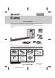
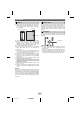
ENGLISH MODEL HT-SB600 SOUND BAR SYSTEM OPERATION MANUAL Thank you for purchasing this SHARP product. To obtain the best performance from this product, please read this manual carefully. It will guide you in operating your SHARP product. HT-SB600 Sound Bar system consisting of HT-SB600 (main unit), CP-SB600 (sound bar) and CP-SW600 (subwoofer).
Special Notes Note to CATV system installer: This reminder is provided to call the CATV system installer’s attention to Article 820 of the National Electrical Code that provides guidelines for proper grounding and, in particular, specifies that the cable ground shall be connected to the grounding system of the building, as close to the point of cable entry as practical. CAUTION: TO REDUCE THE RISK OF ELECTRIC SHOCK, DO NOT REMOVE COVER (OR BACK). NO USER-SERVICEABLE PARTS INSIDE.
Important Safety Instructions (continued) 8) Do not install near any heat sources such as radiators, heat registers, stoves, or other apparatus (including amplifiers) that produce heat. 9) Do not defeat the safety purpose of the polarized or grounding-type plug. A polarized plug has two blades with one wider than the other. A grounding type plug has two blades and a third grounding prong. The wide blade or the third prong are provided for your safety.
For U.S. customer only CONSUMER LIMITED WARRANTY SHARP ELECTRONICS CORPORATION warrants to the first consumer purchaser that this Sharp brand product (the "Product"), when ship in its original container, will be free from defective workmanship and materials, and agrees that it will, at its option, either repair the defect or replace the defective Product or part thereof with a new or remanufactured equivalent at no charge to the purchaser for parts or labor for the period(s) set forth below.
Precautions General Volume control ● Please ensure that the equipment is positioned in a well-ventilated area and ensure that there is at least 4" (10 cm) of free space along the sides, top and back of the equipment. 4" (10 cm) 4" (10 cm) 4" (10 cm) The sound level at a given volume setting depends on speaker efficiency, location and various other factors.
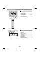
Controls and indicators 1 2 Front Panel 3 Reference page 1. Remote Sensor . . . . . . . . . . . . . . . . . . . . . . . . . . 15 2. Information Display . . . . . . . . . . . . . . . . . . . . . . . 16 3. Timer Indicator . . . . . . . . . . . . . . . . . . . . . . . . . . . 20 4. On/Stand-by Button . . . . . . . . . . . . . . . . . 16, 18, 22 5. Input Button . . . . . . . . . . . . . . . . . . . . . . . 12, 15, 17 6. Equalizer Button . . . . . . . . . . . . . . . . . . . . . . 16, 22 7.
Controls and indicators (continued) Rear Panel 1 2 3 4 Reference page 1. Digital Input Jack. . . . . . . . . . . . . . . . . . . . . . 13, 14 2. Line Input Jack . . . . . . . . . . . . . . . . . . . . . . . 13, 14 3. FM 75 Ohms Antenna Jack. . . . . . . . . . . . . . 11, 12 4. AM Antenna Ground Terminal . . . . . . . . . . . . . . 11 5. AM Loop Antenna Terminal . . . . . . . . . . . . . . . . 11 6. Front Speaker Terminal. . . . . . . . . . . . . . . . . . . . 11 7. Center Speaker Terminal . . . . . . . .
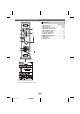
Controls and indicators (continued) Sound Bar FRONT VIEW 1 3 2 4 2 2 REAR VIEW 5 6 7 Reference page 5. Right Front Speaker terminal . . . . . . . . . . . . . . . .11 6. Center Speaker terminal . . . . . . . . . . . . . . . . . . . .11 7. Left Front Speaker terminal . . . . . . . . . . . . . . . . .11 1. Left Front Speaker 2. Bass Reflex Duct 3. Right Front speaker 4. Center Speaker Subwoofer FRONT VIEW REAR VIEW 2 1 3 SUBWOOFER SYSTEM Reference page 1. Bass Reflect Duct 2. Woofer 3.
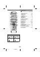
Controls and indicators (continued) 1 Remote Control Reference page 2 HDMI ARC 3 1 2 1 2 1 CLOCK TIMER TV 4 5 DIGITAL 1. Remote Control Transmitter . . . . . . . . . . . . . . . . 15 2. On/Stand-by Button. . . . . . . . . . . . . . . . . . . . 16, 18 3. TV ARC Button. . . . . . . . . . . . . . . . . . . . . . . . 12, 17 4. DIGITAL 1-2 Button . . . . . . . . . . . . . . . . . . . . 15, 17 5. CLOCK Button . . . . . . . . . . . . . . . . . . . . . . . . 16, 19 6. TUNING Up/Down Button . . . . .
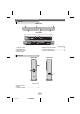
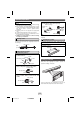
Speaker preparation To mount the speaker on the wall 4 Screw the wall mount angle to the wall as shown in Caution: ● Be very careful to prevent the speaker [ 4.41 lbs. (2.0 kg)] from falling when mounting on the wall. ● Before mounting, check the wall strength. (Do not put on the veneer plaster or whitewashed wall. The speaker may fall.) If unsure, consult a qualified service technician. ● Mounting screws are not supplied. Use appropriate ones. ● Check all wall mount angle screws for looseness.
Placing the system Installation image: Placing the stand Place the stand as shown. TV SUBWOOFER SYSTEM SUBWOOFER SYSTEM Stand SUBWOOFER SYSTEM VCR DVD player Main Subwoofer unit Place the system as shown. Remove the protective film covering the main unit and subwoofer before turn on the system. Notes: ● As the sound from the system is omni-directional, you can place the speaker anywhere you like. However, it is recommended to place it as close to the TV as possible.
System connections Make sure to unplug the AC power cord before making any connections. Main unit Subwoofer FM antenna Red Green White AM loop antenna Sound Bar AC outlet AC 120 - 60 Hz SPEAKERS – + FRONT INPUT CENTER SUB WOOFER Purple Speaker and Subwoofer connection Connect the wire without insulation tube to the minus (-) terminal, and the wire with colored insulation tube to the plus (+) terminal. Make sure to match the colored insulation tube with terminal color before connection.
System connections (continued) TV Antenna connection Supplied FM antenna: Connect the FM antenna wire to the FM 75 OHMS jack and position the FM FM antenna wire in the direction where the antenna strongest signal can be received. DVD, Blu-ray disc player or similar To HDMI (ARC) input terminal Supplied AM loop antenna: Connect the AM loop antenna to the AM and GND (Ground) terminals. Position the AM loop antenna for optimum reception. Place the AM loop on a shelf, etc.
Audio connections to TVs, DVD players, VCRs, etc. Other connection (without HDMI) The illustration below shows the flows of audio and video signals. Audio signal Video signal TV DVD/Blu-ray Disc Player VCR/Game console Digital tuner, etc. Notes: ● Refer to the operation manual of the equipment to be connected. ● Fully insert the plugs to avoid fuzzy pictures or noises. Connecting a TV, etc. Connect to the TV using an optical digital audio cable or an audio cable.
Audio connections to TVs, DVD players, VCRs, etc. (continued) Connecting a DVD player, etc. Connect to the DVD player with an optical digital audio cable or an audio cable.
Remote Control (continued) Audio connections to TVs, DVD players, VCRs, etc. (continued) To select DIGITAL IN 1 (optical input) or DIGITAL IN 2 (coaxial input) function: On main unit: Press INPUT button repeatedly until “DIGITAL 1” or “DIGITAL 2” appears on the display. On remote Press the “DIGITAL 1” or “DIGITAL 2” control: button. To select LINE IN 1 or LINE IN 2 function: On main unit: Press INPUT button repeatedly until “LINE 1” or “LINE 2” appears on the display.
General control Volume control Main unit operation: Press the VOLUME + button to increase the volume and the 00 01 02 ..... 99 100 VOLUME – button for decreasing. Remote control operation: Press the VOL + button to increase the volume and the VOL – button to decrease the volume.
General control (continued) Bass control Audio Return Channel (ARC) (Audio Return Channel submenu) 1. Press the BASS/TREBLE button to select “BASS”. 2. Within 5 seconds, press the VOLUME (+ or –) button to adjust the bass. The audio return channel (ARC) function enables an HDMI ARC-capable TV to send the audio stream to the HDMI OUT jack of the receiver. To use this function, you must select the TV ARC input and your TV must supports the ARC function.
Listening to the radio Listening to the radio (continued) Memorizing a station You can store 40 FM stations in memory and recall them at the push of a button. (Preset tuning) HDMI ARC 1 2 1 2 1 CLOCK TIMER TV DIGITAL DIMMER EQUALIZER 3 LINE TUNING 2 1 Perform steps 1 - 3 in “Tuning” on page 18. TUNER(BAND) X-BASS BASS/TREBLE 2 Press the ENTER button to enter the preset tuning MUTE saving mode.
Setting the clock (Remote Control only) Timer operation (Remote Control only) By setting the unit to the correct time, you can use it not only as a clock but also for timer. Setting the timer In this example, the clock is set for the 12-hour (AM 12:00) display. SUBWOOFER LEVEL CENTER LEVEL PRESET 1 Press the CLOCK button. If clock is not set VOL “ADJUST” will blink. Within 5 seconds, press the ENTER button.
Timer operation (Remote Control only) (continued) After completing the setting When the timer setting is completed: The unit is in the timer playback stand-by mode. TIMER When the start time is reached: Unit starts automatically and the volume increases gradually. The unit is operated by the timer. Timer LED indicator flashes When the finish time is reached: The unit is set to the power stand-by mode automatically. To check the timer setting: 1.
Troubleshooting chart Many potential problems can be resolved by the owner without calling a service technician. If something is wrong with this product, check the following before calling your authorized SHARP dealer or service center. Remote control Symptom ● The remote control General does not operate properly. Symptom ● No sound is heard. Possible cause ● ● ● ● ● The sound from subwoofer is not well balanced.
Troubleshooting chart (continued) Error indicators and warnings If such a problem occurs, do the following: 1. Set the unit to the stand-by mode and turn the power on again. 2. If the unit is not restored in the previous operation, unplug and plug in the unit again, and then turn the power on. When you fail to perform operations properly, the following messages are displayed on the unit. Display Meaning ● Malfunction of the surround Factory reset, clearing all memory circuit.
Specifications As part of our policy of continuous improvement, SHARP reserves the right to make design and specification changes for product improvement without prior notice. The performance specification figures indicated are nominal values of production unit. There maybe some deviations from these values in individual unit. Main unit Power source AC 120 - 60 Hz Power 88 W consumption Dimension Width: 4 - 1/2" (103 mm) Height: 16 - 9/16" (421 mm) Depth: 15 - 1/2" (395 mm) Weight 12.34 lbs (5.