XG-PH80W-N XG-PH80X-N Setup Connections OPERATION MANUAL Easy Start MODEL Introduction DATA PROJECTOR Basic Operation Useful Features Appendix
IMPORTANT • For your assistance in reporting the loss or theft of your Projector, please record the Model and Serial Number located on the bottom of the projector and retain this information. • Before recycling the packaging, please ensure that you have checked the contents of the carton thoroughly against the list of “Supplied accessories” on page 11. ii Model No.: Serial No.
SPECIAL NOTE FOR USERS IN THE U.K. The mains lead of this product is fitted with a non-rewireable (moulded) plug incorporating a 10A fuse. Should the fuse need to be replaced, a BSI or ASTA approved BS 1362 fuse marked or and of the same rating as above, which is also indicated on the pin face of the plug, must be used. Always refit the fuse cover after replacing the fuse. Never use the plug without the fuse cover fitted.
The supplied CD-ROM contains operation instructions in English, German, French, Spanish, Italian, Dutch, Swedish, Portuguese, Chinese, Korean and Arabic. Carefully read through the operation instructions before operating the projector. Die mitgelieferte CD-ROM enthält Bedienungsanleitungen in Englisch, Deutsch, Französisch, Spanisch, Italienisch, Niederländisch, Schwedisch, Portugiesisch, Chinesisch, Koreanisch und Arabisch.
Introduction Introduction Before using the projector, please read this operation manual carefully. ENGLISH There are two important reasons for prompt warranty registration of your new SHARP Projector, using the REGISTRATION CARD packed with the projector. 1. WARRANTY This is to assure that you immediately receive the full benefit of the parts, service and labor warranty applicable to your purchase. 2.
INFORMATION This equipment has been tested and found to comply with the limits for a Class A digital device, pursuant to Part 15 of the FCC Rules. These limits are designed to provide reasonable protection against harmful interference when the equipment is operated in a commercial environment. This equipment generates, uses, and can radiate radio frequency energy and, if not installed and used in accordance with the operation manual, may cause harmful interference to radio communications.
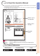
Introduction How to Read this Operation Manual ■ The specifications are slightly different, depending on the model. However, you can connect and operate all models in the same manner. • In this operation manual, the illustration and the screen display are simplified for explanation, and may differ slightly from the actual display.
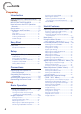
Contents Preparing Introduction How to Read this Operation Manual ......3 Contents .................................................4 IMPORTANT SAFEGUARDS ..................6 How to Access the PDF Operation Manuals..............................................10 Accessories ..........................................11 Part Names and Functions ...................13 Top View ................................................ 13 Front View .............................................. 13 Side View (Terminals) .
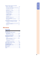
Introduction Adjusting the Projector Function (“PRJ - ADJ” Menu) ...........................52 Detecting the Input Signals Automatically .. 52 Auto Power Off Function ........................ 52 Auto Restart Function ............................. 52 Eco+Quiet .............................................. 52 Setting the Lamp Mode .......................... 53 Setting the Audio .................................... 53 Using the Ex. Setting .............................. 53 Fan Mode Setting ..................
IMPORTANT SAFEGUARDS CAUTION: Please read all of these instructions before you operate this product and save these instructions for later use. Electrical energy can perform many useful functions. This product has been engineered and manufactured to assure your personal safety. BUT IMPROPER USE CAN RESULT IN POTENTIAL ELECTRICAL SHOCK OR FIRE HAZARDS. In order not to defeat the safeguards incorporated in this product, observe the following basic rules for its installation, use and servicing. 1.
Do not overload wall outlets, extension cords, or integral convenience receptacles as this can result in a risk of fire or electric shock. 16. Object and Liquid Entry Never push objects of any kind into this product through openings as they may touch dangerous voltage points or short-out parts that could result in a fire or electric shock. Never spill liquid of any kind on the product. 17.
Observe the following safeguards when setting up your projector. Caution concerning the lamp unit ■ Potential hazard of glass particles if lamp ruptures. In case of lamp rupture, contact your nearest Sharp Authorized Projector Dealer or Service Center for replacement. See “Regarding the Lamp” on page 66.
■ If you are not to use the projector for a long time or before moving the projector, make certain you unplug the power cord from the wall outlet, and disconnect any other cables connected to it. ■ Do not carry the projector by holding the lens. ■ When storing the projector, ensure you attach the lens cap or dustproof cap to the projector. ■ Do not expose the projector to direct sunlight or place next to heat sources. Doing so may affect the cabinet color or cause deformation of the plastic cover.
How to Access the PDF Operation Manuals PDF operation manuals in several languages are included in the CD-ROM. To utilize these manuals, you need to install Adobe® Reader ® on your computer (Windows® or Macintosh®). Please download Adobe® Reader ® from the Internet (http://www.adobe.com). Accessing the PDF Manuals For Windows®: Insert the CD-ROM in the CD-ROM drive. Double click the “My Computer” icon. Double click the “CD-ROM” drive.
Introduction Accessories Supplied accessories Dustproof cap <9NK3392038200> Remote control <9NK5041821400> Power cord* (1) Two R-6 batteries (“AAA” size, UM/SUM-4, HP-7 or similar) (2) RGB cable (6' (1.8 m)) <9NK3081405002> (3) Anti-theft screw <9NK3100132500> (4) For U.S., Canada, etc. For Europe, except U.K. For U.K., Hong Kong (6 n (1.8 m)) (6 n (1.8 m)) and Singapore <9NK3090204900> <9NK3090152701> (6 n (1.8 m)) <9NK3090152901> For Australia, New Zealand and Oceania (6 n (1.
Accessories (Continued) Optional accessories Projection Distance for 100" Screen Size Lens Type XG-PH80W-N XG-PH80X-N Fixed wide lens (× 0.8) AN-PH808EX 5'6" (1.7 m) 5'2" (1.6 m) Wide-zoom lens (× 1.3 – 1.8) AN-PH814EZ 9'5" (2.9 m) – 12'8" (3.9 m) 8'10" (2.7 m) – 11'11" (3.6 m) Standard zoom lens (× 1.8 – 2.4) AN-PH818EZ 12'7" (3.8 m) – 16'7" (5.1 m) 11'10" (3.6 m) – 15'8" (4.8 m) Tele-zoom lens (× 2.2 – 4.4) AN-PH823EZ 15'8" (4.8 m) – 31'4" (9.5 m) 14'10" (4.5 m) – 29'6" (9.
Introduction Part Names and Functions Numbers in Z refer to the main pages in this operation manual where the topic is explained. Top View 1 9 1 FOCUS buttons 31 For adjusting the focus. 2 H&V LENS SHIFT (P/R/O/Q) buttons 30 For shifting the lens horizontally and vertically. 2 3 MENU button 41 For displaying adjustment and setting screens. 4 Adjustment buttons (P/R/O/Q) 41 For selecting menu items. 3 5 ENTER button 33 For setting items selected or adjusted on the menu.
Part Names and Functions (Continued) Numbers in Z refer to the main pages in this operation manual where the topic is explained. 1 2 3 4 5 6 7 8 9 10 11 12 13 11 14 15 16 17 18 Terminal for computer RGB and component signals and audio input terminal. 9 10 11 12 19 Side View (Terminals) 1 COMPUTER/COMPONENT1 input terminals 21, 23 2 LAN terminal 25 Terminal for controlling the projector using a computer via network.
Introduction Numbers in Z refer to the main pages in this operation manual where the topic is explained. 7 AUTO SYNC button 36 For automatically adjusting images when connected to a computer. 8 LENS SHIFT button 30 1 10 9 3D MODE button 59 For displaying the 3D MODE menu screen. 2 3 For displaying the lens shift adjustment screen. 10 INPUT button 33 For switching Input mode.
Part Names and Functions (Continued) Inserting the Batteries 1 Remove the cover by sliding towards the direction of the arrow. 2 Insert the batteries. 3 Replace the cover. • Insert the batteries making sure the polarities correctly match the m and n marks inside the battery compartment. Incorrect use of the batteries may cause them to leak or explode. Please follow the precautions below Caution • Danger of explosion if battery is incorrectly replaced.
Easy Start This section shows the basic operation (projector connecting with the computer). For details, see the page described below for each step. Setup and Projection In this section, connection of the projector and the computer is explained using one example. 7 6 5 7 8 4 10 8 5 4 10 Easy Start 6 8 5 7 8 6 6 7 5 1. Remove the dustproof cap and then attach the optional BP. 26 lens 2. Place the projector facing a wall or a screen BP. 19 3.
Easy Start (Continued) 5. Adjust the angle Adjust the projector angle: • Shift the lens horizontally and vertically. - Press H&V LENS SHIFT (P/R/O/Q) on the projector. - Press LENS SHIFT and then press P, R, O or Q on the remote control. • Adjust the projector angle by rotating the adjustment feet. BP. 30 6. Adjust the focus and the zoom 1 2 Press FOCUS +/– on the projector or on the remote control to adjust the focus. Press ZOOM +/– on the projector or on the remote control to adjust the zoom. BP.
Setting Up the Projector Video Setup If using this projector outside the U.S.A., please change setting to “0 IRE” in Video Setup. (See page 48.) Setting Up the Projector For optimal image quality, position the projector perpendicular to the screen with the projector's feet flat and level. Doing so will eliminate the need for Keystone correction and provide the best image quality. (See page 32.
Setting Up the Projector (Continued) Projection (PRJ) Mode The projector can use any of the 4 projection modes shown in the diagram below. Select the mode most appropriate for the projection setting in use. (You can set the PRJ mode in “SCRADJ” menu. See page 49.
Connecting the Projector to Other Equipment Before connecting, ensure that the power cord of the projector is unplugged from the AC outlet and turn off the equipment to be connected. After making all connections, turn on the projector and then the other pieces of equipment. When connecting a computer, ensure that it is the last equipment to be turned on after all the connections are made.
Connecting the Projector to Other Equipment (Continued) Equipment Video equipment, Camera, Video game Terminal on connected equipment Cable DVI digital output terminal DVI Digital cable (commercially available) Audio output terminal ø3.5 mm stereo minijack to RCA audio cable (commercially available) RGB video output terminal 5 BNC cable (commercially available) Audio output terminal ø3.
Equipment Video equipment, Camera, Video game Terminal on connected equipment D-video output terminal Cable Cables for a camera or a video game/3 RCA to mini D-sub 15 pin cable (optional, AN-C3CP2) Terminal on the projector COMPUTER/ COMPONENT1 RCA adaptor plug (commercially available) Audio output terminal ø3.
Controlling the Projector by a Computer When the RS-232C terminal on the projector is connected to the RS-232C serial terminal on the computer, or when the LAN terminal on the projector is connected to the LAN terminal on the computer, the computer can be used to control the projector. Refer to the “SETUP MANUAL” contained on the supplied CD-ROM for details.
When connecting to the LAN terminal using a LAN cable TX/RX LED (yellow) Illuminates when transmitting/receiving data. LINK LED (green) Illuminates when linked. * To ensure safety, do not connect the LAN terminal with any cables that may cause excessive voltage such as a telephone line. Hub or Computer To LAN terminal Connections LAN cable (Category 5 type, commercially available) Note • When you establish the connection shown above, set “LAN/RS232C” in “Ex. Setting” of the “PRJADJ” menu to “LAN”.
Attaching the Optional Lens When you attach a lens for the first time, skip steps 1 to 3. (When you replace the lens, start from step 1.) STANDBY/ON button Do not attempt to exchange the lens when the projector is installed hanging from the ceiling. Injury may occur if the lens falls. 1 Press STANDBY/ON on the projector or on the remote control to put the projector into standby mode. • Switch the MAIN POWER switch on the projector to “OFF”.
5 Insert the replacement lens with the top position mark on it facing up, and then turn the lens clockwise until you hear a click sound. • Make sure that the lens cannot be released even when you try to turn the lens anti-clockwise and pull it out. Top position mark Using the Anti-Theft Screw Connections • The lens is secured by the above method, but for added security, an anti-theft screw is supplied to secure the lens more tightly.
Turning the Projector On/Off Info Turning the Projector On Note that the connections to external equipment and power outlet should be done before performing the operations written below. (See pages 21 to 25.) Remove the lens cap. Then switch the MAIN POWER switch on the projector to “ON” and, after the POWER indicator has turned red, press STANDBY/ON on the projector or on the remote control.
Image Projection Shifting the Lens In addition to the zoom function and adjustment of projection angle using the adjustment feet, you can adjust the position of the projection using the lens shift function. This is a useful function in cases such as when the screen cannot be moved. When moving upward or downward When moving in the left and right direction Adjustable rang e Adjustable rang e Adjustable range Adjustable range • The adjustable range is shown below.
Image Projection (Continued) 1 Press H&V LENS SHIFT (P/R/O/ Q) on the projector, or press LENS SHIFT and P/R/O/Q on the remote control, to adjust the image position. Adjustment buttons (P/R/O/Q) ROn-screen display LENS SHIFT button LENS SHIFT H&V LENS SHIFT (P/R/O/Q) buttons Using the Adjustment Feet • When the position of the projected image cannot be adjusted with the lens shift function, use the adjustment feet to adjust the projected angle.
Adjusting the Focus Press FOCUS +/– on the projector or on the remote control to adjust the focus. Info FOCUS buttons ZOOM buttons • It is recommended that the focus be adjusted after the projector has warmed up for at least 30 minutes. Adjusting the Projected Image Size Press ZOOM +/– on the projector or on the remote control to adjust the projected image size.
Image Projection (Continued) Correcting Trapezoidal Distortion When the image is projected either from the top or from the bottom towards the screen at an angle, the image becomes distorted trapezoidally. The function for correcting trapezoidal distortion is called Keystone Correction. Adjustment buttons (P/R/O/Q) On-screen display (Keystone Correction mode) MENU button Note Keystone 0 Shrinks upper side. (Move the slide bar in the + direction.
INPUT button Adjusting the Volume Press VOL +/– on the remote control to adjust the volume. (ENTER) button P/R buttons On-screen display Volume 1 Note VOL +/– (Volume) buttons AV MUTE button Switching the Input Mode Select the appropriate Input mode for the connected equipment. Press INPUT on the projector or on the remote control to display the INPUT list. • Pressing VOL– will lower the volume. • Pressing VOL+ will raise the volume.
Image Projection (Continued) Resize Mode This function allows you to modify or customize the Resize mode to enhance the input image. You can set the Resize mode in “SCR-ADJ” menu. See page 49.VID 1 Press MENU to display the menu screen, and then press O or Q to select “SCR-ADJ”. 2 Press P or R to select “Resize”. 3 Press O or Q to adjust the desired Resize mode and then press (ENTER).
RESIZE Output screen image 4:3 An image stretched from a 4:3 aspect ratio to a 16:9 aspect ratio is restored to a 4:3 aspect ratio. Native The image is displayed according to the original input signal. “Native” cannot be selected when the input mode is VIDEO or S-VIDEO. About Copyrights • When using the Resize function to select an image size with a different aspect ratio to a TV program or video image, the image will look different from its original appearance.
Operating with the Remote Control Auto Sync (Auto Sync Adjustment) Auto Sync function works when detecting input signal after the projector turns on. Press AUTO SYNC to manually adjust with Auto Sync function. Note • When the optimum image cannot be achieved with Auto Sync adjustment, use manual adjustments. (See page 46.) AUTO SYNC button FREEZE button Freezing a Moving Image 36 1 Press FREEZE. 2 Press FREEZE again to return to the moving image from the currently connected device.
Using the Remote Control to Operate the Computer When connecting the projector and the computer with a USB cable, you can use the remote control to operate the computer. Connecting with a USB cable Computer To USB terminal To USB terminal USB cable (commercially available or available as Sharp service part QCNWGA014WJPZ) The computer can be operated in the following way after it is connected. ■ When moving the cursor s s Same as the [ / / r / s ] keys on a computer keyboard.
Menu Items The following shows the items that can be set in the projector. “Picture” menu Main menu Picture Page 43 Sub menu Presentation Standard Game Movie sRGB Picture Mode Page 43 Bright Boost 0 2 Bright -30 +30 Contrast -30 +30 Color -30 +30 Tint -30 +30 Sharp -30 +30 Page 44 Ex. Setting Auto RGB YCbCr YPbPr Signal Type Page 44 Page 44 CLR Temp -1 1 Page 44 Red -30 +30 Blue -30 +30 Page 44 C.M.S.
“Signal adjustment (SIG-ADJ)” menu Main menu SIG-ADJ Page 46 Sub menu H-Pos -150 +150 V-Pos -60 +60 Phase -30 +30 Clock -150 +150 “Screen adjustment (SCR-ADJ)” menu Main menu SCR - ADJ Page 49 Sub menu English Deutsch polski magyar nyelv Español Nederlands Türkçe Français Italiano Svenska Português Language Page 49 Reset Page 46 Resolution Page 46 Background Logo Custom Blue None Page 49 Auto Wide 4:3 Front Rear Ceiling + Front Ceiling + Rear PRJ Mode Auto Sync [On/Off] Page 49
Menu Items (Continued) “Projector adjustment (PRJ-ADJ)” menu Main menu PRJ - ADJ Page 52 Sub menu Auto Search [On/Off] Page 52 Auto Power Off [On/Off] Page 52 Auto Restart [On/Off] Page 52 Eco + Quiet [On/Off] Page 52 Lamp Mode Page 53 Audio Page 53 Ex.
Using the Menu Screen Adjustment buttons (P/R/O/Q) MENU button Adjustment buttons (P/R/O/Q) MENU button RETURN button • Press RETURN to return to the previous screen when the menu is displayed. Menu Selections (Adjustments) Example: Adjusting “Bright”. • This operation can also be performed by using the buttons on the projector. 1 2 Press MENU. • The menu screen is displayed. Press Q or O and select “Picture” to adjust.
Using the Menu Screen (Continued) 3 Press P or R and select “Bright” to adjust. • The selected item is highlighted. Picture SIG-ADJ Video SCR-ADJ Picture Mode PRJ-ADJ Presentation Bright Boost 2 Bright 0 Contrast 0 Color 0 Tint 0 Sharp 0 Ex. Setting Reset MENU = END SEL./ADJ. SEL. Items to be adjusted Picture 4 Press O or Q to adjust the item selected. • The adjustment is stored.
Picture Adjustment (“Picture” Menu) Menu operation n Page 41 SIG-ADJ Picture Video SCR-ADJ Picture Mode PRJ-ADJ Picture SIG-ADJ Presentation Video SCR-ADJ PRJ-ADJ Ex. Setting Bright Boost 2 Signal Type Bright 0 CLR Temp Auto 0 Contrast 0 Red 0 Color 0 Blue 0 Tint 0 C.M.S. Sharp 0 Film Mode Auto DNR Ex. Setting Level 1 Dynamic Black Reset MENU = END SEL./ADJ. SEL. MENU = END Off SEL./ADJ. SEL.
Picture Adjustment (“Picture” Menu) (Continued) Menu operation n Page 41 2 Adjusting the Image Adjustment items O button Adjusting the Color Temperature Q button Selectable items To improve color reproduction, lower bright boost setting. To increase brightness, increase bright boost setting. Bright For less brightness. For more brightness. 0 Contrast For less contrast. For more contrast. 1 Color*1 For less color intensity. For more color intensity. Tint*1 For making skin tones purplish.
Menu operation n Page 41 7 Adjusting the Colors This function adjusts each of the six main colors that comprise the color wheel, altering their “Hue”, “Saturation”, or “Value”. Selectable items Description Hue Sets the hue of the main colors. Saturation Sets the saturation of the main colors. Value Selecting the Film Mode This function provides high-quality playback of images originally projected at 24 fps, such as movies on DVDs. Selectable items Auto Films are detected automatically.
Signal Adjustment (“SIG-ADJ” Menu) Menu operation n Page 41 Picture SIG-ADJ Video SCR-ADJ PRJ-ADJ H-Pos 0 V-Pos 0 Phase 0 Clock 0 Reset Resolution Auto Auto Sync Off MENU = END SEL./ADJ. 1 Adjusting the Computer Image If the optimum image cannot be obtained with Auto Sync adjustment, use the SIG-ADJ function. Selectable items Centers the on-screen image by moving it to the left or right. V-Pos Centers the on-screen image by moving it up or down.
Video Adjustment (“Video” Menu) Menu operation n Page 41 Picture SIG-ADJ Video SCR-ADJ PRJ-ADJ Overscan On Video System Auto Video Setup 7.5 IRE Closed Caption MENU = END 1 Setting the Overscan This function allows you to set the overscan area (display area). Selectable items Description On The input area is displayed without the screen edges. Off The whole input area is displayed. Off SEL./ADJ. SEL.
Video Adjustment (“Video” Menu) (Continued) Menu operation n Page 41 3 Setting the Video Setup Selectable items Description 0 IRE Sets the black level to 0 IRE. 7.5 IRE Sets the black level to 7.5 IRE. Note • This function is available for the following signals. With COMPUTER/COMPONENT1, 2 or COMPONENT input: - 480I With S-VIDEO or VIDEO input: - NTSC3.58 4 Closed Caption Info • This function is available for NTSC3.58 signal.
Adjusting the Projected Image (“SCR-ADJ” Menu) Menu operation n Page 41 Picture SIG-ADJ Video SCR-ADJ PRJ-ADJ Language Picture SIG-ADJ English Logo Security Lock PRJ Mode Front Keypad Lock Normal Keystone SCR-ADJ PRJ-ADJ Ex. Setting Background Resize Video Disable Image Capture 0 Image Resizing 0 Wall Color Off Ex. Setting MENU = END SEL./ADJ. SEL. 1 Selecting the On-screen Display Language The projector can switch the on-screen display language among 15 languages.
Adjusting the Projected Image (“SCR-ADJ” Menu) (Continued) Menu operation n Page 41 5 Keystone Correction When the image is projected either from the top or from the bottom towards the screen at an angle, the image becomes distorted trapezoidally. The function for correcting trapezoidal distortion is called Keystone Correction. Select “Keystone” on the “SCR-ADJ” menu and adjust with the slide bar. See page 32 for details of “Correcting Trapezoidal Distortion”.
Menu operation n Page 41 9 Security Lock Function This function prevents unauthorized use of the projector. Once this function is activated, users must enter the correct password each time the projector is turned on. We suggest you record the password in a safe place where only authorized users have access. 0 Keypad Lock Function Use this function to lock the operation buttons on the projector. Selectable items No Turns off the Keypad Lock function.
Adjusting the Projector Function (“PRJ-ADJ” Menu) Menu operation n Page 41 Picture SIG-ADJ Video SCR-ADJ PRJ-ADJ Picture SIG-ADJ Auto Search Off Auto Power Off Off Fan Mode Auto Restart Off STANDBY Mode ECO + Quiet Off Standby Audio Out Lamp Mode Both Lamps Video SCR-ADJ PRJ-ADJ Ex. Setting Normal Standard On Filter Message Audio 3D MODE Ex. Setting LAN/RS232C Reset Network 500H LAN Information MENU = END SEL./ADJ. SEL.
Menu operation n Page 41 5 Setting the Lamp Mode This function allows you to select the usage of the two lamps installed in the projector. Selectable items Both Lamps Description Both lamps are used for greater brightness. Lamp 1 Only The lamp 1 is used. When the lamp 1 burns out, the lamp 2 automatically switches in use. Lamp 2 Only The lamp 2 is used. When the lamp 2 burns out, the lamp 1 automatically switches in use. Equal Use The lamp whose remaining life time is the longer is used.
Adjusting the Projector Function (“PRJ-ADJ” Menu) (Continued) Menu operation n Page 41 ■ IP Address/Subnet Mask/Gateway/ DNS/Apply Filter Message You can select the interval time to display a message for cleaning the filter. Clean The Filter. Selectable items Selectable items Factory default setting: 192.168.150.002 Enter an IP address appropriate for the network. Subnet Mask Factory default setting: 255.255.255.000 Set the subnet mask to the same as that of the computer and equipment on the network.
Menu operation n Page 41 Returning to the Default Settings ■ All Reset This function allows you to initialize the settings you have made in the projector. Note • The following items or menu cannot be initialized. - Lamp Timer (Life) - Filter Timer - Image stored using “Image Capture” ■ Filter Timer Reset This function allows you to reset the filter timer. Information You can confirm the following items. Displayed items Description INPUT Used input terminal is displayed.
Viewing Stereoscopic 3D Images Precautions on Viewing Stereoscopic 3D Images Before viewing stereoscopic 3D images, please read this section carefully. WARNING ■ Under normal conditions, viewing stereoscopic 3D images is safe for any duration that you would normally view your screen. However, some people may experience discomfort. The following precautions are recommended to minimize the potential for experiencing visual problems or any adverse symptoms.
WARNING ■ The following people should limit stereoscopic 3D viewing: – Children under 6 years of age (to protect the eye growth process) – People with a history of photosensitivity – People with heart disease – People in poor health – People who are sleep deprived – People who are physically tired – People under the influence of drugs or alcohol ■ Epilepsy A small percentage of the population may experience epileptic seizures when viewing certain types of images that contain flashing patterns of light.
Viewing Stereoscopic 3D Images (Continued) Information on the 3D Projection Function • To display 3D images, this projector requires: WHAT YOU WILL NEED 1) Source devices that support the field sequential format – For details on the supported signals, see the Compatibility Chart in this operation manual. 2) 3D LCD shutter glasses that support the DLP® Link™* system – Contact your nearest Sharp Authorized Projector Dealer for purchasing details. * DLP® Link™ is a trademark of Texas Instruments.
Using 3D Viewing Mode Use the following procedure to project 3D images. For operation of the 3D LCD shutter glasses and the 3D-video playback equipment, see the corresponding operation manual. 7 Press P or R to select “DLP® Link™”, and then select “On”. 8 Select “DLP® Link™ Invert”, and then press (ENTER) to switch the mode and enable more natural 3D image viewing.
Viewing Stereoscopic 3D Images (Continued) Appendix ■ How the 3D Projection Function (DLP Link™ ) Works The 3D projection function of this projector is compatible with the DLP® Link™ system. To watch 3D images, you use a pair of 3D LCD shutter glasses that alternately display the projected images for the left and right eyes and are synchronized with a control (light) signal.
Maintenance Cleaning the projector ■ Ensure that you have unplugged the power cord before cleaning the projector. ■ The cabinet as well as the operation panel is made of plastic. Avoid using benzene or thinner, as these can damage the finish on the cabinet. ■ Do not use volatile agents such as insecticides on the projector. Do not attach rubber or plastic items to the projector for long periods. The effects of some of the agents in the plastic may cause damage to the quality or finish of the projector.
Cleaning and Replacing the Dust Filters When the message shown below is displayed, clean or replace the three dust filters and then reset the filter timer (see page 55). You must clean or replace all three dust filters at the same time to synchronize the filter timer. Clean The Filter. Cleaning the Dust Filters Use a vacuum cleaner to clean dust from the exhaust vent and the intake vent (bottom, side and rear). Info • The dust filters should be cleaned every 100 hours of use.
2 Remove the filter covers. • Remove the filter covers towards the direction of the arrow. Front Side Rear 3 Pick the dust filters up and lift them out of all the three filter covers as shown in the figures. 4 Place replacement dust filters and press them down firmly. 5 Replace the filter covers. • Insert the filter covers and push them gently as shown in the figure.
Maintenance Indicators ■ The warning lights (POWER indicator, TEMP. (temperature warning)/STATUS indicator and LAMP indicator) on the projector indicate problems inside the projector. ■ If a problem occurs, either the TEMP. (temperature warning)/STATUS indicator or the LAMP indicator will illuminate red, and the projector will enter Standby mode. After the projector has entered Standby mode, follow the procedures given below. Top View LAMP (1, 2) indicators TEMP.
Maintenance indicator Normal TEMP. (temperature warning)/ STATUS indicator Off Abnormal Problem Possible Solution Red blinks The TEMP. • The lamp unit cover (temperature is open. warning)/STATUS indicator blinks in red when the projector is on. • If the TEMP. (temperature warning)/STATUS indicator blinks in red even when the lamp unit cover are securely installed, contact your nearest Sharp Authorized Projector Dealer or Service Center (see page 76) for advice.
Regarding the Lamp Lamp ■ It is recommended that the lamp (sold separately) be replaced when the remaining lamp life becomes 5% or less, or when you notice a significant deterioration in the picture and color quality. The lamp life (percentage) can be checked with the on-screen display. (See page 55.) ■ Purchase a replacement lamp of type AN-PH80LP from your place of purchase, nearest Sharp Authorized Projector Dealer or Service Center. IMPORTANT NOTE TO U.S.
Removing and Installing the Lamp Unit Info • Do not touch the glass surface of the lamp unit or the inside of the projector. • To avoid injury to yourself and damage to the lamp, make sure you carefully follow the steps below. • Do not loosen other screws except for the lamp unit cover and lamp unit. Warning! • Do not remove the lamp unit from the projector right after use. The lamp and parts around the lamp will be very hot and may cause burns or injury.
Regarding the Lamp (Continued) 5 Insert the new lamp unit. 6 Replace the lamp unit cover. • Press the lamp unit firmly into the lamp unit compartment. Fasten the securing screw. • Align the lamp unit cover and slide it to close (1). Then tighten the user service screw (2) to secure the lamp unit cover. Info • If the lamp unit and lamp unit cover are not correctly installed, the power will not turn on, even if the power cord is connected to the projector.
Replacing the Color Wheel The projector is equipped with a four-segment color wheel. You can replace it with a six-segment color wheel (sold separately). The replacement procedure described below also applies when you put the four-segment color wheel back in the place of the six-segment one. Warning! • Do not remove the color wheel from the projector right after use. The lamp and parts around the lamp will be very hot and may cause burns or injury.
Replacing the Color Wheel (Continued) 4 Loosen the 4 retaining screws from the four-segment color wheel. 5 Hold the color wheel and pull it in the direction of the arrow. Caution The module contains components that can be damaged or destroyed by electrostatic discharge. Please pick the module with the handle. 6 Insert the six-segment color wheel, and tighten the 4 retaining screws. 7 Replace the lamp unit cover. • Align the lamp unit cover and slide it to close (1).
Compatibility Chart Computer • Multiple signal support Horizontal Frequency: 15, 31-90 kHz, Vertical Frequency: 50-85 Hz, PC/MAC Mode Resolution VGA 640 × 480 SVGA 800 × 600 XGA 1024 × 768 PC 1280 × 720 1280 × 768 WXGA 1280 × 800 WXGA+ 1360 × 768 1366 × 768 1440 × 900 1152 × 864 1280 × 960 SXGA 1280 × 1024 MAC 13” MAC 16” MAC 19” MAC 21” SXGA+ WSXGA+ UXGA VGA SVGA XGA SXGA 1400 × 1050 1680 × 1050 1600 × 1200 640 × 480 832 × 624 1024 × 768 1152 × 870 Pixel Clock: 12-165 MHz Sync signal: Co
Compatibility Chart (Continued) 3D Supported Signals Signal Horizontal Frequency (kHz) SVGA 800 × 600 XGA 1024 × 768 1280 × 800 WXGA 1280 × 720 37.9 77.1 48.4 98.6 49.7 101.6 45.0 92.6 Vertical Frequency (Hz) 60 120 60 120 60 120 *1 60 120 Analog Support ✔ ✔ ✔ ✔ ✔ ✔ ✔ ✔ Digital Support ✔ ✔ ✔ ✔ ✔ ✔ ✔ ✔ *1 Reduced Blanking Note • Your computer graphics card must be able to display 3D stereoscopic signals.
Troubleshooting Problem • • • • • • No picture and no sound • or projector does not • start. • • • • • Check Projector power cord is not plugged into the wall outlet. Power to the external connected devices is off. The selected Input mode is wrong. The AV Mute function is working. Cables are incorrectly connected to the projector. Remote control battery has run out. External output has not been set when connecting notebook computer.
Troubleshooting (Continued) Problem Check Page • Make the necessary adjustments of each item in the “SIG-ADJ” menu. 46 • Depending on the computer you are using, the output resolution signal – may be different from the one you have set. For details, refer to the operation manual of the computer. • If the picture is normal, the sound is due to cabinet shrinkage caused – An unusual sound is by room temperature changes. This will not affect operation or occasionally heard from performance. the cabinet.
Problem Check • Images may appear to flicker when fluorescent light or ambient light enters your vision. – Turn off the lights. – Block any ambient light. Ghosting (a double image) • Check that you are using 3D LCD shutter glasses that support the ® occurs without the image DLP Link™ system. – Be sure to use 3D LCD shutter glasses that support the DLP® Link™ appearing in 3D. system. • Check that the shutters on the 3D LCD shutter glasses are working properly.
For SHARP Assistance If you encounter any problems during setup or operation of this projector, first refer to the “Troubleshooting” section on pages 73 to 75. If this operation manual does not answer your question, please contact the SHARP Service departments listed below. U.S.A. Sharp Electronics Corporation 1-888-GO-SHARP (1-888-467-4277) lcdsupport@sharpsec.com http://www.sharpusa.com Canada Sharp Electronics of Canada Ltd. (905) 568-7140 http://www.sharp.
Specifications Model Display devices Resolution Optional Lens (Standard) (AN-PH818EZ) Lens shift Input terminals Output terminals Control and communication terminals F number Zoom Focus DVI-D (Compatible with HDCP) Computer/Component (5BNC) Computer/Component (D-sub 15 pin) Component (RCA) S-Video (mini DIN 4 pin) Video (RCA) Audio (ø3.5 mm stereo minijack) Audio (RCA) Computer/Component (D-sub 15 pin) Audio (ø3.
Dimensions 15 11/64 (385) Units: inches (mm) /8 (3) 3 7/16 (87) 7 41/64 (194) 4 1/4 (108) 1 4 13/64 (106.5) 9 /64 19 57/64 (505) (252.5) 9 61/64 (252.5) 3 29/32 (99) 61 5 11/32 (135.7) 8 49/64 (222.5) 4 59/64 (125) 8 49/64 (222.5) 4 59/64 (125) 1 3/16 (30) 4 13/64 (106.5) M4 M4 78 5 29/64 (138.5) 2 15/64 (56.5) 4 (101.
Index 4:3·····················································································35 16:9···················································································34 3D MODE ·········································································54 3D MODE button ······························································15 Accessories ······································································11 AC socket ··································································