SERVICE MANUAL CODE: 00ZAL840//B1E BASIC MANUAL DIGITAL COPIER MODEL AL-800/840 CONTENTS [ 1 ] OPERATING PRINCIPLE . . . . . . . . . . . . . . . . . . . . . . . . . . . . . . . . 1-1 1. Block diagram . . . . . . . . . . . . . . . . . . . . . . . . . . . . . . . . . . . . . . . . . . . . 1-1 2. Outline of operations . . . . . . . . . . . . . . . . . . . . . . . . . . . . . . . . . . . . . . 1-3 A. Paper path and imaging . . . . . . . . . . . . . . . . . . . . . . . . . . . . . . . . . . . 1-3 B.
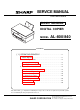
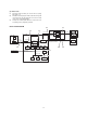
SCANNER (READING) SECTION Control signal, detection signal, drive signal, control data line DOCUMENT COPY LAMP Image data signal line Image (light) SCANNER HOME POSITION SENSOR LENS MIRROR LIGHT QUANTITY SENSOR SCANNER MOTOR CCD Power line OPERATION PWB COPY LAMP CONTROL PWB A/D ONVERTOR CPU MEMORY PARALLEL I/F Paper path line ASIC LAMP (LED) ICU PWB HOST(PC) KEY MEMORY ASIC FAN MOTOR SCANNER (WRITE) SECTION MCU (PCU) PWB LASER DIODO 1–1 MAIN MOTOR MOTOR DRIVER LENS MIRROR LAS
Scanner (writing) section Scanner (reading) section Fusing/paper exit section Image process section Paper feed section The operations of this section are composed of five processes; exposure, development, transfer, separation, and discharge.
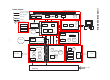
2. Outline of operations A. Paper path and imaging Paper is fed, transported, and discharged through the path indicated with the arrow in the figure below. 1) Paper feed (Paper on the paper tray is fed to the transfer section by the paper feed roller.) 2) Image transfer (The toner image on the photoconductor is transferred onto the paper by the transfer roller.) 3) Fusing (The toner image on the paper is fused by the heat roller and the pressure roller.
(2) Printer mode P1) Print data (compressed data) are sent from the host. (Image data (Data 1 – 8) P2) Print data are developed by the ASIC and the line memory and converted into the full dot image data and sent to the data select section. (Image data)(VIDEO) P3) The data are sent through the data select section to the scanner (writing) section.
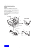
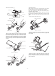
3. Operations of each section A. Paper feed, paper transport section (1) Outline The paper feed tray contains about 200 (250) sheets of paper. The paper is passed to the transfer section by the paper feed roller. The paper feed operation is controlled by the paper feed roller clutch and the paper feed roller clutch solenoid. The paper feed clutch employs the mechanical spring clutch. Paper mis-feed and paper jam are detected by the paper empty sensor and the paper entry sensor.
No. 1 Parts Code PE SENSOR Signal name PEMP IN Name Paper empty detector Type Function/operation Photo transmission sensor Detects paper on the paper tray. 2 Paper guide Adjust the paper width. 3 Paper feed tray Sets the print paper. (Capacity: XXX sheets) 4 Paper release lever Put this lever straight to set paper to release paper feed. Put this lever down to enable paper feed. Paper feed clutch solenoid Controls (on/off) the main motor drive for the paper feed roller.
(3) Operation a. Block diagram MCU(PCU)PWB High voltage power PWB +24V ASIC (IC8) CN805 Paper pickup solenoid 1 +24V 2 PUS PUS MEN CN804 MMT0 MMT1 1 2 3 4 Motor driver CPU MA MAMB MB- Main motor (IC5) +5V PIN PD801 Paper entry roller Paper feed roller +5V POUT- CN7 1 +5V 2 POUT 3 GND PD802 LSU PWB PE CN9 9 PE CN601 9 PE Paper exit roller +24V PD601 Paper empty roller * Paper release lever b.
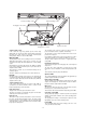
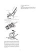
(Paper fixing operation) (Paper release operation) Notch When the paper release lever is pushed down, the paper release lever arm pushes the lock lever arm in the direction of arrow (A). Lower frame By the above operation, the rotating disk is lifted and the paper is pushed by the paper feed roller.
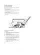
B. Scanner (reading) section (1) Outline In this section, the copy lamp (Xenon lamp) radiates light onto a document, and the reflected light is detected by the image sensor (CCD element) to convert into electrical signals (analog signals), which are sent to the MCU PWB. Paper feed roller Separate sheet The paper feed roller is of circular form, and double paper feed is prevented by the separate sheet.
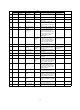
(2) Major parts 10) 11) 1) 2) 4) MHPS 6) CCD SENSOR 8) SL SENSOR 5) 3) 2) 7) 4) MHPS 10) 8) SL SENSOR 7) 6) CCD SENSOR 9) 11) No. 1 Name Scanner lamp control PWB 2 Scanner drive wire 3 4 Code MHPS Signal name MHPS 5 6 Photo transmission sensor Lens CCD SENSOR CCD OUT 7 8 Scanner motor Scanner home position sensor Parts Type CCD (Image) sensor CCD Scanner lamp SL SENSOR PDA/PDK Scanner lamp light quantity sensor 9 No. 1 mirror 10 No. 2 mirror 11 No.
(3) Operation a.
* CCD unit * Scanner home position sensor Images (light) is converted into an electrical signal (analog signal) by the CCD. The scanner home position sensor senses the scanner position. The copy image position control is performed by the sensing timing of this sensor. The image signal read by the CCD is converted into a digital signal b the A/D convertor in the MCU PWB and outputted to the ASIC, where the image is processed.
Parts No. 1 Code Signal name SYNC SYNC IN Name Type Laser beam sensor Function/operation Bin diode Active condition Detects the laser beam position. By this signal the left image print start position is controlled. Note LOW (0V) when laser beam is detected. 2 No. 1 mirror 3 No. 3 mirror Leads the laser beam to the OPC drum. 4 Second cylindrical lens Corrects the laser beam deflection by variations in the scanning mirror angle. Corrects the optical section dirt. 5 Fθ mirror (No.
The scanning mirror is a 6-surface mirror. Six lines are printed for one rotation of the scanning motor. Laser beams reflected by the scanning mirror are passed to the curved mirror by the No. 1 reflection mirror. Before reaching the curved mirror, the laser beams enter the laser beam sensor on the start position detection PWB to make horizontal synchronization (generating SYNC signal). The laser beams from No. 1 reflection mirror are arranged to be parallel beams by the curved mirror and passed to No.
(2) Image forming process diagram Scanning mirror High voltage circuit Laser diode Lens No. 1 No.
(3) Major parts a. Photoconductor section 1) 5) 6) 3) 5) 4) 2) 1) Parts No. Name Type OPC Note Function/operation 1 OPC drum 2 OPC drum earth electrode Forms latent electrostatic images. Connects the OPC drum aluminum layer and the earth (high voltage PWB). 3 Main charger electrode Connects the main charger output (high voltage PWB) and the main charger brush. 4 Discharge brush Discharges (lower the potential of) the OPC drum surface. 5 Main charger brush Charges the OPC drum.
b. Development section 5) 2) 1) 7) 8) 5) 1) 3) 3) 6) 4) 4) 8) 5) 1) No. Parts Name Type Function/operation 1 Developing roller Attaches toner to the latent electrostatic images on the OPC drum to convert it into a visible image. 2 Developing doctor Controls toner quantity on the developing roller and charges toner. 3 Developing bias electrode Connects the developing roller and the bias voltage output (high voltage PWB).
c. Transfer/separation section 1) 3) 4) 3) 5) 2) 1) No. 4) Parts Name Function/operation 1 Transfer roller Transfers toner images on the OPC drum onto the paper. 2 Transfer roller electrode Connects the transfer roller and the transfer voltage output (high voltage PWB). 3 Pressure spring Applies pressure to the transfer roller, paper, and the OPC drum to improve transfer efficiency. 4 Separation electrode Reduces paper charging potential to facilitate separation of paper.
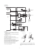
(4) System diagram Scanning mirror Laser beam Laser unit MCU PWB No. 1 - 4 mirror Image data Toner High voltage power PWB –310V/+200V selection Main charger brush DC –310V DC-310V Developing roller DC +200V Photoconductor drum DC +3.5KV AC600V(P-P) DC-200V Discharge brush DC –850V Paper Transfer charger roller DC-850V AC600V(P-P) Separation electrode DC+500V (5) Operation a.
b. Major parts functions and operations <2> Developing unit Visible images are formed with toner over the latent electrostatic images formed on the OPC drum surface. Toner is filled in the developing unit. 1) Developing roller 3) The developing roller is made of urethane and it has considerably high electrical resistance. It is flexible and pressed onto the OPC drum. Toner is attached to the latent electrostatic images on the OPC drum to make visible images.
c. Actual image forming process Step 2 (Exposure); Laser beam scanning light corresponding to the print data is radiated onto the OPC drum. Step 1 (Cleaning, charging): Residual toner on the OPC drum is stirred and negative charges are distributed evenly on the OPC drum. (The OPC drum is evenly charged.) Positive and negative charges are generated in the CGL of the OPC drum which are radiated with laser beams.
Step 3 (Development): Toner is attached to the latent electrostatic images formed on the OPC drum. At that time, the potential of the OPC drum surface where there is no charge by exposure of laser beams is higher than the developing roller potential. On the other hand, there are negative charges in the OPC drum surface area which is not exposed to laser beams. When that area is brought into contact with the developing roller, if toner is attached to the OPC drum,.
The positive charges are attracted to the OPC drum which is negatively charged, and put on the paper transported between the transfer roller and the OPC drum. The paper, therefore, is charged positively. Step 6 (Discharging): The drum surface is discharged by the discharge brush to facilitate cleaning. (Residual toner can be easily collected by the main charger roller.
d.
E. Fusing/paper exit section (1) Outline Toner attracted to the paper in the transfer section is fused by heat and pressure of the heat roller. The heat roller is of thin aluminum roller which is high heat conductivity, minimizing the warm up time. The heat roller surface temperature is detected by the fusing temperature sensor to maintain the fusing temperature at a constant level (160/155 ˚C).
(3) Operation a. Wiring diagram MCU(PCU) PWB POWER SUPPLY PWB Fusing section AC POWER IN CPU (IC5) CN603 1/3 HLL HLON- HLON Temperature fuse (132 C) Gate Temperature fuse (187 C) Heater lamp RTH CN603 2/4 HLN COMP AMP ASIC (IC202) PR Thermistor CN2 GND 1 RTHN 2 RTH PR CN801 +24V DRIVER High voltage power PWB 1 +24V 2 NC 3 +24VS b.
F. Drive section (1) Outline The main motor drives the paper feed section, the transport section, the image process section, and the fusing section . The main motor drive circuit is built in the high voltage power PWB. (2) Major parts 1) 3) 2) No. 1 Parts Code MM Name Main motor Type Note Function, operation Stepping motor (+24V) Drives the paper feed section, the paper transport section, the fusing section, and the image process section.
G.
MCU PWB BLOCK DIAGRAM SCANNER MOTOR HOME POSITION SENSOR MRMT0~3 MHPS_IN CN11 CN12 INVERTOR PWB CCD PWB f1,f2, SH-,RS, CCDOUT SP,CP CLCNT CN10 IC13 CN13 CN14 IC112 PSIZE_IN PAPER SIZE SENSOR CN9 VDATA IC8 ASIC HG73C025FD IC5 CPU H8S/2350 LASER PMCLK PMD- LSU PWB RTH_IN THERMISTOR CN8 PSIZE_IN PAPER EMPTY SENSOR DSRDY-,RESERRDPAGE-,VIDEO VSYNC-,PRSTT RESET,DREADYDCRDY-,ERROR SCLK,SYNC ICU PWB CN2 PAPER EXIT SENSOR CN7 PEMP_IN POLYGON MOTOR CN1 OPCLK,OPLATCH OPPSW OPDATA,SE
q COPYRIGHT 1998 BY SHARP CORPORATION All rights reserved. Printed in Japan. No part of this publication may be reproduced, stored in a retrieval system, or transmitted. In any form or by any means, electronic, mechanical, photocopying, recording, or otherwise, without prior written permission of the publisher.