MODEL PG-M20X Setup and Connections Basic Operation Easy to Use Functions DIGITAL MULTIMEDIA PROJECTOR Introduction OPERATION MANUAL Appendix
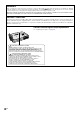
IMPORTANT For your assistance in reporting the loss or theft of your Projector, please record the Serial Number located on the bottom of the projector and retain this information. Before recycling the packaging, please be sure that you have checked the contents of the carton thoroughly against the list of “Supplied accessories” on page 14. Model No.: PG-M20X Serial No.: This equipment complies with the requirements of Directives 89/336/EEC and 73/23/EEC as amended by 93/68/ EEC.
SPECIAL NOTE FOR USERS IN THE U.K. The mains lead of this product is fitted with a non-rewireable (moulded) plug incorporating a 13A fuse. Should or and of the same rating as the fuse need to be replaced, a BSI or ASTA approved BS 1362 fuse marked above, which is also indicated on the pin face of the plug, must be used. Always refit the fuse cover after replacing the fuse. Never use the plug without the fuse cover fitted.
The supplied CD-ROM contains operation instructions in English, German, French, Swedish, Spanish, Italian, Dutch, Portuguese, Chinese (Traditional Chinese and Simplified Chinese), Korean and Arabic. Carefully read through the operation instructions before operating the projector.
Before using the projector, please read this operation manual carefully. ENGLISH Introduction Introduction There are two important reasons for prompt warranty registration of your new SHARP Projector, using the REGISTRATION CARD packed with the projector. 1. WARRANTY This is to assure that you immediately receive the full benefit of the parts, service and labor warranty applicable to your purchase. 2.
WARNING: The cooling fan in this projector continues to run for about 90 seconds after the projector is turned off. During normal operation, when turning the power off always use the POWER button on the projector or on the remote control. Ensure the cooling fan has stopped before disconnecting the power cord. DURING NORMAL OPERATION, NEVER TURN THE PROJECTOR OFF BY DISCONNECTING THE POWER CORD. FAILURE TO OBSERVE THIS WILL RESULT IN PREMATURE LAMP FAILURE.
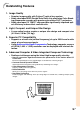
Outstanding Features Introduction 1. Image Quality • Superior image quality with Fujinon™ optical lens system • Newly developed DDR (Double Data Rate) chip eliminates Color Breaking phenomena common with previous generation DLP™ projectors. • Newly developed 12° DMD™ chip provides significantly improved optical efficiency and excellent contrast ratio. 2. Light, Compact, and Unique Slim Design • A new optical engine creates a unique slim design and compact size (4.2 liters, 5.8 lbs. (2.6 kg)). 3.
Contents Introduction Adjusting the Picture ........................................ 40 Outstanding Features ......................................... 3 Contents ............................................................... 4 IMPORTANT SAFEGUARDS ............................... 6 How to Access the PDF Operation Manuals ..... 9 Part Names ........................................................ 10 Projector (Front and Top View) ................................ 10 Projector (Side View) ...................
Introduction Setting the Anti-Theft ........................................ 63 Entering the Keycode .............................................. 63 Changing the Keycode ........................................... 64 Initializing the Settings ..................................... 65 Displaying the Adjustment Settings ................ 66 Appendix Carrying the Projector ...................................... Maintenance ...................................................... Maintenance Indicators .......
IMPORTANT SAFEGUARDS CAUTION: Please read all of these instructions before you operate this product and save these instructions for later use. Electrical energy can perform many useful functions. This product has been engineered and manufactured to assure your personal safety. BUT IMPROPER USE CAN RESULT IN POTENTIAL ELECTRICAL SHOCK OR FIRE HAZARDS. In order not to defeat the safeguards incorporated in this product, observe the following basic rules for its installation, use and servicing. 1.
Introduction 19. Replacement Parts 18. Damage Requiring Service Unplug this product from the wall outlet and refer servicing to qualified service personnel under the following conditions: a. When the power-supply cord or plug is damaged. b. If liquid has been spilled, or objects have fallen into the product. c. If the product has been exposed to rain or water. d. If the product does not operate normally by following the operating instructions.
IMPORTANT SAFEGUARDS (cont.) Be sure to read the following safeguards when setting up your projector. Caution concerning the lamp unit ■ Potential hazard of glass particles if lamp ruptures. In case of lamp rupture, contact your nearest Sharp Authorized Projector Dealer or Service Center for a replacement. See “Replacing the Lamp” on page 71.
How to Access the PDF Operation Manuals Introduction PDF operation manuals in several languages are included in the CD-ROM. To utilize these manuals, you need to install Adobe Acrobat Reader on your PC (Windows or Macintosh). If you have not installed Acrobat Reader yet, you can download it from the Internet (http:// www.adobe.com) or install it from the CD-ROM. To install Acrobat Reader from the CD-ROM For Windows: 1 Insert the CD-ROM in the CD-ROM drive. 2 Double click on the “My Computer” icon.
Part Names Projector (Front and Top View) LAMP REPLACEMENT indicator 70 70 Illuminates in green normally. When the internal temperature rises, this indicator will illuminate in red. Illuminates in green normally. Replace the lamp when the indicator illuminates in red. POWER indicator 28 Illuminates in red, when the projector is in standby. When the power is turned on, this indicator will illuminate in green. 29 28 32 29 36 33 36 44 For setting items selected or adjusted on the menu.
Introduction Projector (Side View) INPUT 1 terminal 21 26 USB terminal For connecting a computer using a USB cable. Port for DVI digital, computer RGB, and COMPONENT signals. INPUT 2 terminal 24 Terminal for connecting video equipment with an S-VIDEO terminal. AC socket 20 21 INPUT AUDIO terminal Shared audio terminal for INPUT 1, INPUT 2, and INPUT 3. 24 INPUT 3 terminal For connecting video equipment.
Part Names (cont.) Remote Control Remote control signal transmitter FORWARD/BACK button 26 Moves forward or backwards when connected to a computer using a USB cable. Same as the [Page Down] and [Page Up] keys on a computer keyboard. AV MUTE button 49 30 48 29 29 29 29 46 LENS button 50 ENTER button For setting items selected or adjusted on the menu. GAMMA button For correcting the brightness of an image, when the images displayed are hard to see because of the brightness of the room.
Using the Remote Control Introduction Available Range of the Remote Control ■ The remote control can be used to control the projector within the ranges shown in the illustration. Note • The signal from the remote control can be reflected off a screen for easy operation. However, the effective distance of the signal may differ due to the screen material. 30° Remote control 45° sensor 23' (7 m) When using the remote control: • Be sure not to drop, expose to moisture or high temperature.
Accessories Supplied accessories Remote control RRMCGA013WJSA Power cord (6' (1.8m)) (1) For U.S., Canada, etc. QACCDA007WJPZ Two R-03 batteries (“AAA” size, UM/SUM-4, HP-16 or similar) (2) (3) For Europe, except U.K. QACCV4002CEZZ For U.K., Hong Kong and Singapore QACCB5024CENA (4) For Australia, New Zealand and Oceania QACCL3022CEZZ Note • Depending on the region, projectors only ship with one power cord (see above). Use the power cord that corresponds to the wall outlet in your country.
Setup and Connections Setup and Connections
Setup Foot releases Adjustment feet Using the Adjustment Feet The height of the projector can be adjusted using the adjustment feet when the surface of the projector is placed on is uneven or when the screen is slanted. The projection of the image can be made higher by adjusting the projector when it is in a location lower than the screen. 1 Press the foot releases. 2 Lift the projector to adjust its height and remove your hands from the foot releases.
Setting up the Screen Position the projector perpendicular to the screen with all feet flat and level to achieve an optimal image. Note Standard Setup (Front Projection) ■ Place the projector at the required distance from the screen according to the desired picture size. (See page 18.) Example of Standard Setup • The distance from the screen to the projec- Side View tor may vary depending on the size of the screen. P.
Setup (cont.) Screen Size and Projection Distance Screen Base line: Horizontal line passing through the lens center. Lens center 90° H L:Projection distance NORMAL Mode (4:3) Picture (Screen) size Diag. (X) Width Projection distance (L) Height Maximum (L1) Minimum (L2) – Distance from the lens center to the bottom of the image (H) 300" (762 cm) 240" (610 cm) 180" (457 cm) 39' 5" (12.0 m) 0" (0.0 cm) 250" (635 cm) 200" (508 cm) 150" (381 cm) 39' 8" (12.1 m) 32' 10" (10.0 m) 0" (0.
Projecting a Reversed/Inverted Image Projection from behind the screen ■ Place a translucent screen between the projector and the audience. ■ Reverse the image by setting “Rear” in “PRJ Mode”. See page 60 for use of this function. When using the default setting. ▼On-screen Display Setup and Connections Projection using a mirror ■ Place a mirror (normal flat type) in front of the lens. ■ Reverse the image by setting “Rear” in “PRJ Mode”, when the mirror is placed on the audience side.
Connecting the Projector to Other Devices Before Connecting Note • Before connecting, be sure to turn off both the projector and the devices to be connected. After making all connections, turn on the projector and then the other devices. When connecting a computer, be sure that it is the last device to be turned on after all the connections are made. • Be sure to read the operation manuals of the devices to be connected before making connections.
Connecting the Projector to a Computer Connecting to a Computer Using the DVI to 15-pin D-sub Cable DVI to 15-pin D-sub cable To RGB Output port To Audio Output port Connect the projector to the computer using the supplied DVI to 15-pin D-sub cable. Notebook computer • Secure the connectors by tightening the thumbscrews. 2 To input audio signal, connect the projector to the computer using a ø3.5 mm stereo audio cable (commercially available or available as Sharp service part QCNW-4870CEZZ). 2 ø3.
Connecting the Projector to Other Devices (cont.) Connecting to a Computer Using a DVI Cable (Sold Separately) This projector comes installed with a DVI digital input terminal in which computer digital image signals can be directly input. 1 Connect the projector to the computer using the DVI cable. 2 To input audio signal, connect the projector to the computer using a ø3.5 mm stereo audio cable (commercially available or available as Sharp service part QCNW-4870CEZZ).
Connecting to Video Equipment Connecting to Component Video Equipment Optional accessories *DTV is the umbrella term used to describe the new digital television system in the United States. 1 Connect the 3 RCA to 15-pin Dsub cable using the DVI to 15pin D-sub adaptor. 2 Use the above cables to connect the projector and the video equipment. DVI to 15-pin D-sub adaptor Model: AN-A1DV (7.
Connecting the Projector to Other Devices (cont.) Connecting to Video Equipment Using an S-VIDEO, a Composite Video or an Audio Cable Using an S-VIDEO, video, or audio cable, a VCR, laser disc player or other audio-visual equipment can be connected to INPUT 2, INPUT 3 and AUDIO terminals. 1 2 Connect the projector to the video equipment using an SVIDEO cable or a composite video cable (both commercially available).
Connecting to a Monitor Watching Images on Both the Projector and a Monitor Setup and Connections You can display computer images on both the projector and a separate monitor using an RGB monitor loop-out adaptor and an RGB cable. RGB monitor loop-out adaptor Type: AN-A1MY (7.9" (20 cm)) Optional accessory To RGB input port Monitor 1 2 Connect the projector to the computer and monitor using an RGB monitor loop-out adaptor (sold separately) and an RGB cable (commercially available).
Connecting the Projector to Other Devices (cont.) Using the Wireless Presentation Function of the Remote Control The Wireless Presentation function on the projector works the same as the [Page Up] and [Page Down] keys on a computer keyboard. It can also be used to move forward or backward when viewing images of presentation software such as Power PointTM. Using the Wireless Presentation Function 1 Connect the projector to the computer using the supplied USB cable.
Basic Operation Basic Operation
Image Projection ▼Projector indicators Basic Procedure Connect the required external equipment to the projector before operating the following procedures. The language preset at the factory is English. If you want to change the on-screen display to another language, reset the language according to the procedure on page 30. 1 LAMP REPLACEMENT indicator POWER indicator Plug the power cord into the wall outlet. • The POWER indicator illuminates up in red, and the projector enters standby mode.
"On-screen Display (Example) Press , or on the remote control to select the INPUT Mode.
Image Projection (cont.) 5 Press to temporarily turn off the picture and sound. AV MUTE button Note • Pressing again will turn the picture and the sound back on. 6 Press , then press again while the confirmation message is displayed, to turn off the projector. Note • If you accidentally pressed and do not want to turn off the power, wait until the confirmation message disappears. Info • Do not unplug the power cord during projection or cooling fan operation.
3 Press or to select the desired language, and then . press 4 Press . • The desired language will be set as the on-screen display. Zoom knob Adjusting the Lens The image is focused and adjusted to the desired size using the focus ring or zoom knob on the projector. Basic Operation Focus ring 1 The focus is adjusted by rotating the focus ring. 2 Zooming is adjusted by moving the zoom knob.
Correcting the Trapezoidal Distortion (Keystone Correction) Correcting the Trapezoidal Distortion This function allows for Keystone (On-screen Trapezoidal Distortion) Correction. LENS button ENTER button Note • Keystone Correction is the correction for trapezoidal distortion that occurs when the image is positioned away from the center axis of the screen. • The trapezoidal distortion can be corrected up to an angle of approximately ±35 degrees. 1 Press 2 Press or to adjust the Keystone correction.
Digital Shift Setting For easier viewing, this function shifts the entire image projected on the screen up or down when projecting 16:9 images from DVD players and DTV* decoders. * DTV is the umbrella term used to describe the new digital television system in the United States. Press to move the projected image upwards. Press image. UNDO button to reset the Press to move the projected image downwards. Press image.
Menu Bar Items This list shows the items that can be set in the projector.
■ INPUT 2 / 3 Mode Main menu Sub menu Main menu Sub menu Picture Contrast –30 +30 Options (2) Lamp Timer Page 40 Bright –30 +30 Page 58 Break Timer Color –30 +30 Tint –30 +30 Sharp –30 +30 Red –30 +30 Blue –30 +30 CLR Temp –3 +3 PRJ Mode Front Ceiling + Front Rear Ceiling + Rear Keylock Level Normal Level A Level B Password Old Password New Password Reconfirm Anti-Theft Old Code New Code Reconfirm Reset Progressive Mode 2D Progressive 3D Progressive Film Mode All
Using the Menu Screen This projector has two sets of menu screens that allow you to adjust the image and various projector settings. You can operate the menus from the projector or remote control using the following procedure. On-screen menu for INPUT 2 or INPUT 3 Mode On-screen menu for INPUT 1 RGB mode Menu Bar (Main Menu) Menu Bar (Main Menu) MENU button Basic Operations (Adjustments) 1 Press buttons . Note • The “Picture” menu screen for the selected input mode is displayed.
2 Press or to select the menu you want to adjust. Note • For details on the menus, see the tree charts on pages 34 and 35. 3 Press or to select the item you want to adjust. Note • To display a single adjustment item, press after selecting the item. Only the menu bar and the selected adjustment item will be displayed. Then if you press or , the following item (“Phase” is after “Clock”) will be displayed. • Press Basic Operation | to return to the previous screen. 4 Press or item selected.
Using the Menu Screen (cont.) MENU button Basic Operations (Settings) 1 Press buttons . Note • The “Picture” menu screen for the selected input mode is displayed. • The on-screen display shown on the right is displayed when the INPUT 1 mode is selected. 2 ENTER button Press or to select the menu you want to adjust. MENU button Note buttons • For details on the menus, see the tree charts on pages 34 and 35. ENTER button 3 ▼ On-screen Display Press or to select the item you want to set.
4 Press . • The cursor shifts to the sub menu. Sub menu Press or to select the setting of the item displayed in the sub menu. 6 Press Basic Operation 5 . • The item selected is set. Note • Some adjustment items will display a confirmation message. When setting an item, press or to select “Yes” or “OK” and then press . 7 Press . • The menu will disappear.
Adjusting the Picture You can adjust the projector’s picture to your preferences with the following picture settings.
Progressive Mode This function allows you to select the progressive display of a video signal. The progressive display projects a smoother video image. Select “Progressive Mode” in the “Picture” menu ➝ For settings, see page 38. Note • Basic Operation 2D Progressive This function is useful to display fastmoving images such as sports and action films. This mode optimizes the image in a displayed frame.
Adjusting Computer Images Use the Fine Sync function in case of irregularities such as vertical stripes or flickering in portions of the screen. Selected Item Description Clock Adjusts vertical noise. Phase Adjusts horizontal noise (similar to tracking on your VCR). H-Pos Centers the on-screen image by moving it to the left or right. V-Pos Centers the on-screen image by moving it up or down.
Selecting Adjustment Settings Adjustment settings stored in the projector can be easily accessed. Select “Select Setting” in the “Fine Sync” menu ➝ For details, see page 38. Note • If a memory position has not been set, a resolution and frequency setting will not be displayed. • When selecting a stored adjustment setting with “Select Setting”, you can set the projector in the stored adjustments.
Adjusting Computer Images (cont.) Auto Sync Adjustment Used to automatically adjust a computer image. Select “Auto Sync” in the “Fine Sync” menu ➝ For settings, see page 38. Note When setting to “ Normal” or High Speed”: “ • Auto Sync adjustment will occur when the projector is turned on or when the inputs are switched, when connected to a computer. Manual adjustments should be performed: • When the optimum image cannot be achieved with Auto Sync adjustment. See page 42.
Easy to Use Functions Easy to Use Functions
Selecting the Picture Display Mode This function allows you to modify or customize the picture display mode to enhance the input image. Depending on the input signal, you can choose “NORMAL”, “FULL”, “DOT BY DOT”, “BORDER”, “STRETCH” or “SMART STRETCH” image. Switching the Picture Display Using Different Input Signals 1 Press . • Each time is pressed, the display changes as shown on page 47.
COMPUTER NORMAL 1024 × 768 1024 × 768 1024 × 768 1024 × 768 960 × 768 SVGA (800 × 600) XGA (1024 × 768) SXGA (1280 × 960) UXGA (1600 × 1200) SXGA (1280 × 1024) 4:3 aspect ratio Other aspect ratios FULL — — — — 1024 × 768 DOT BY DOT 800 × 600 — 1280 × 960 1600 × 1200 1280 × 1024 • “NORMAL” is fixed when XGA (1024 × 768) signals are entered.
Displaying a Still Image This function allows you to instantly freeze a moving image. This is useful when you want to display a still image from a computer or video, giving you more time to explain the image to the audience. Storing an Image in Still Image Format 1 Press . • The projected image is frozen. FREEZE button "On-screen Display 2 48 -48 Press again to return to the moving image from the currently connected device.
Enlarging a Specific Portion of an Image This function allows you to enlarge a specific portion of an image. This is useful when you want to display a detailed portion of the image. Displaying an Enlarged Portion of an Image 1 Press . • Enlarges the image. or enlarges or re• Pressing duces the projected image. ENLARGE (Enlarge/ Reduce) buttons Note buttons To enlarge ×1 ×2 ×3 ×4 ×9 ×16 ×36 ×64 To reduce • You can change the location of the enlarged image using , , or .
Gamma Correction Function Gamma is an image quality enhancement function that offers a richer image by brightening the darker portions of the image without altering the brightness of the brighter portions. When you are displaying images with frequent dark scenes, such as a film or concert, or when you are displaying images in a bright room, this feature makes the dark scenes easier to see and gives the impression of greater depth in the image.
Displaying Dual Pictures (Pict in Pict) Picture in Picture function allows you to display two pictures on the same screen. You can display the image input from INPUT 2 or 3 as an inset picture overlapping the main picture from INPUT 1. (This function can only be set in the RGB menu.) Displaying the Inset Picture Select “Pict in Pict” in the “Options (1)” menu ➝ For displaying, see page 36. 1 Press • Select to select . to clear the Pict in Pict mode.
Selecting the Power Save Mode The Power Save Mode or the Automatic Power Shutoff function allows you to reduce the power consumption of the projector. Setting the Power Save Mode Function to control the quantity of projected light. Select “ON” or “OFF” to decrease or increase brightness and power consumption. Description of Power Save Modes Quantity of light is 80%. Power consumption is 250W. Quantity of light is 100%. Power consumption is 290W.
Activating the sRGB Color Management Function This function calibrates the projector’s output to conform to sRGB standard (6,500K). Setting the Color Management Function (sRGB) Select “sRGB” in the “Options (1)” menu ➝ For settings, see page 36. Note • When setting sRGB to “ON”, the projected image may become dark; however, this does not indicate a malfunction. • For additional information about sRGB function, please visit “http://www.srgb.com/”.
Video Digital Noise Reduction (DNR) System Digital Noise Reduction (DNR) provides high quality images with minimal dot crawl and cross color noise. Reducing Image Noise (DNR) Select “DNR” in the “Options (1)” menu ➝ For settings, see page 38. Note • Set a level so as to view a clearer picture. Make sure to set DNR to “OFF” in the following cases: • When the image is blurry. • When the contours and colors of moving images drag. • When TV broadcasts with weak signals are projected.
Setting the Video Signal The video input system mode is preset to “Auto”; however, a clear picture from the connected audio-visual equipment may not be received, depending on the video signal difference. In that case, switch the video signal. Setting the Video Signal Select “Video System” in the “Options (1)” menu ➝ For settings, see page 38. Note • The video signal can only be set in INPUT 2 or INPUT 3 mode. • In “Auto”, images are displayed in PAL even if PAL-N or PAL-M input signals are received.
Saving Projected Images • This projector allows you to capture projected images (RGB signals) and set them as a startup image, or background image when no signals are being received. • You can capture the images that are input using analog RGB signals and Digital DVI XGA signals. Capturing the Image Select “Image Capture” in the “Options (1)” menu ➝ For details, see page 38. 1 Press or to select “ Save Image” and press . • The projected image is captured. It may take some time for capturing.
Setting a Background Image This function allows you to select the image displayed when no signal is being sent to the projector. Selected Item Description Sharp SHARP default image Custom *1 User customized image (i.e. company logo) Blue Blue screen None Black screen *2 *1 You can set a captured image as a background image in “Image Capture”. *2 If the input signal has interference, the screen will be displayed with the interference.
Using an RGB Monitor Loop-out Adaptor Using an RGB monitor loop-out adaptor (sold separately) and an RGB cable (commercially available), be sure to set to “ Yes (Y Cable)” when you want to display computer images both on the projector and on a monitor. Using a RGB Monitor Loop-out Adaptor Select “Monitor Out” in the “Options (1)” menu ➝ For settings, see page 38. Note • Be sure to set to “ Disable” when not using an RGB monitor loop-out adaptor.
Displaying the Break Timer Displaying and Setting the Break Timer Select “Break Timer” from the “Options (2)” menu ➝ For details, see page 36. 1 When “ or Timer. ” is displayed, press to set the Break "On-screen Display • You can set anywhere between 1 and 60 minutes (in 1 minute units). 2 Press Timer. to cancel the Break Note Easy to Use Functions • Auto Power Off will be temporarily disabled during the Break Timer.
Reversing/Inverting Projected Images This projector is equipped with a reserve/invert image function that allows you to reverse or invert the projected image for various applications. Selected Item Description Front Normal image Ceiling + Front Inverted image Rear Reversed image Ceiling + Rear Reversed and inverted image Setting the Projection Mode Select “PRJ Mode” in the “Options (2)” menu ➝ For settings, see page 38.
Canceling the Keylock Setting When the Keylock Level is set to “Normal”, all buttons are functional. Select “Keylock Level” in the “Options (2)” menu and set “ Normal”. ➝ For settings, see page 38. Note • When a password has been set, and “Keylock Level” is selected, the password input box will be displayed. • If both a password and the Keylock Level have been set at the same time, the password will be necessary before changing the Keylock Level.
Setting the Anti-Theft The anti-theft function prevents unauthorized use of the projector. You can choose to use this function or not. If you do not want to use this function, just do not enter the keycode. Once the theft-deterrent function is activated, users will need to enter the correct keycode each time the projector is started. Failure to enter the correct keycode will prevent images from being projected. The following procedures explain how to use this function.
Setting the Anti-Theft (cont.) When “Anti-Theft” is set, the keycode inputting section appears after the power is turned on. At that time, enter the right keycode. • Press the buttons on the remote control if the buttons on the remote control are used for setting the keycode. In the same manner, press the buttons on the projector if the buttons on the projector are used for setting the keycode. Info • Once the function is activated, you must remember the correct keycode.
Initializing the Settings This function allows you to initialize the settings you have made in the projector. Returning to the Default Settings Select “All Reset” in the “Options (2)” menu ➝ For resetting, see page 36. Note • If a password has been set, the password input box will be displayed when selecting “All Reset”. The following items cannot be initialized.
Displaying the Adjustment Settings This function can be used to display all the adjusted settings as a list on the screen. Checking the Adjustment Settings on a List Select the “Status” menu and press ➝ For details, see page 36.
Appendix Appendix
Carrying the Projector How to Use the Carrying Case When carrying the projector, attach the lens cap to the lens, and place it in the included carrying case. 1 Open the cover of the carrying case. 2 Remove the inner padding from the carrying case, and fold it in the direction of the arrows. 3 Reinsert the inner padding into the carrying case. Info • Be sure to insert the inner padding to protect the lens and the projector. 4 Place the projector and the accessories in the carrying case.
Maintenance Cleaning the projector Cleaning the lens ■ Be sure to unplug the power cord before cleaning the projector. ■ The cabinet as well as the operation panel is made of plastic. Avoid using benzene or thinner, as these can damage the finish on the cabinet. ■ Do not use volatile agents such as insecticides on the projector. Do not attach rubber or plastic items on the projector for long time. The effects of some of the agents in the plastic may cause damage to the quality or finish of the projector.
Maintenance Indicators ■ The warning lights on the projector indicate problems inside the projector. ■ If a problem occurs, either the TEMPERATURE WARNING indicator or the LAMP REPLACEMENT indicator will illuminate red, and the power will turn off. After the power has been turned off, follow the procedures given below.
Regarding the Lamp Lamp ■ It is recommended that the lamp (sold separately) be replaced after approximately 1,900 cumulative hours of use or when you notice a significant deterioration of the picture and color quality. The lamp usage time can be checked with the on-screen display. See page 58. ■ For lamp replacement, please consult your nearest Sharp Authorized Projector Dealer or Service Center. IMPORTANT NOTE TO U.S.
Regarding the Lamp (cont.) Removing and Installing the Lamp Unit Lamp unit BQC-PGM20X//1 Info • Be sure to remove the lamp unit by the handle. Be sure not to touch the glass surface of the lamp unit or the inside of the projector. • To avoid injury to yourself and damage to the lamp, be sure to carefully follow the steps below. • Do not remove other screws except for the lamp cover screws. • Please refer to the installation manual included with the lamp unit.
4 Remove the lamp unit. 5 Insert the new lamp unit. 6 • Remove the securing screws from the lamp unit. Hold the lamp unit by the handle and pull it in the direction of the arrow. • Press the lamp unit firmly into the lamp unit compartment. Fasten the securing screws. Securing screw Attach the lamp unit cover. • Slide the lamp unit cover in the direction of the arrow. Then tighten the user service screw.
Connecting Pin Assignments DVI Digital / Analog INPUT 1 port : 29 pin connector • DVI Digital INPUT 9 ••••••••• 1 2 •••• Pin No. 1 2 3 4 5 6 7 8 9 10 11 12 13 14 15 ~ • • • • • • • • • 16 ~ •••• 7 8 C1 C2 C4 C5 C3 17 24 18 •••• ~ • • • • 23 • DVI Analog RGB Input Pin No.
Computer Compatibility Chart • Multiple signal support Horizontal Frequency: 15–126 kHz Vertical Frequency: 43–200 Hz* Pixel Clock: 12–230 MHz • Compatible with sync on green and composite sync signals • UXGA and SXGA compatible in advanced intelligent compression • AICS (Advanced Intelligent Compression and Expansion System) resizing technology The following is a list of modes that conform to VESA. However, this projector supports other signals that are not VESA standards.
Troubleshooting Problem Check • Projector power cord is not plugged into the wall outlet. • Power to the external connected devices is off. • The selected input mode is wrong. • Cables incorrectly connected to side panel of the projector. • Remote control batteries have run out. No picture and no sound • External output has not been set when connecting notebook computer. • The AV MUTE display appears. • Cables incorrectly connected to the side panel of the projector. • “Bright” is set to minimum position.
Problem Check Power cannot be turned • The Keylock level is set. on or off using the If the Keylock level is set to Level B, all the buttons are locked. POWER button on the If the Keylock level is set to Level A, only the INPUT, VOLUME projector and AV MUTE buttons work. Picture is green on • Change the input signal type setting. INPUT 1 COMPONENT Picture is pink (no green) on INPUT 1 RGB • The LAMP REPLACEMENT indicator is blinking in red. Replace the lamp.
For SHARP Assistance If you encounter any problems during setup or operation of this projector, first refer to the “Troubleshooting” section on pages 76 and 77. If this operation manual does not answer your question, please contact the SHARP Service departments listed below. U.S.A. Sharp Electronics Corporation 1-888-GO-SHARP (1-888-467-4277) lcdsupport@sharpsec.com http://www.sharplcd.com Canada Sharp Electronics of Canada Ltd. (905) 568-7140 http://www.sharp.
Specifications Product type Digital Multimedia Projector Model PG-M20X Video system NTSC 3.58/NTSC 4.43/PAL/PAL-M/PAL-N/PAL 60/SECAM/ DTV480I/DTV480P/DTV720P/DTV1080I Display method Single Chip Digital Micromirror Device™ (DMD™) by Texas Instruments DMD panel Panel size: 0.7" (17.8 mm), 1 chip XGA DMD No. of dots: 786,432 dots (1,024 [H] × 768 [V]) Lens 1–1.2 × zoom lens, F1.75–2.04, f = 28.0–33.
Dimensions Units: inches (mm) Rear View Side View Top View 12 9/16 (318.3) Side View 11 15/16 (302.5) 8 3/4 (223) 8 5/8 (219) 5 1/16 (128) Front View 1 1/2 3 3 1/4 (38.7) (76.1) (82.9) 1 3/8 (34.2) 4 9/16 (115.5) 7 11/16 (195) 3 1/4 (82.5) 2 3/16 (55.5) 3 1/8 (80) Bottom View -80 2 3/8 (60) 5/16 (7.5) 4 1/8 (104) 10 5/16 (261.
Glossary Advanced intelligent compression High quality resizing of lower and higher resolution images to fit the projector’s native resolution. Anti-theft In case the projector is stolen, this function disables projection of images if the correct keycode is not entered. Aspect Ratio Width and height ratio of an image. The normal aspect ratio of a computer and video image is 4:3. There are also wide images with an aspect ratio of 16:9 and 21:9.
Index 2D Progressive .................................................... 41 3D Progressive .................................................... 41 AC socket ............................................................ 20 Adjustment buttons .............................................. 36 Adjustment feet .................................................... 16 All Reset .............................................................. 65 Anti-Theft .............................................................
SHARP CORPORATION