
Service manual


7
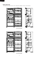
SJ-D30M
SJ-D33M
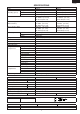
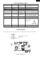
LIST OF ELECTRICAL PARTS
ITEMS TYPE NAME RATING SPECIFICATIONS
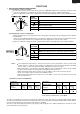
Thermostat MM1-9010 125V 6A (At normal notch)
250V 3A ON/OFF : -19 / -24˚C
Defrost thermostat S101 250V 8A Open/Close : 8 / 1˚C
Thermo. fuse SF70E 250V 10A Working temp. : 70˚C
Fan motor 3R00121A 220-240V 50/60Hz Working with ø100 fan
Defrost heater MM6-4264 220-240V 378Ω 140W at 230V
Door switch SDKNA20101 250V 0.25A 3 terminals push-button type
125V 0.5A
Damper thermostat MM1-6173 — Open/Close : 4.5 / 0˚C
Defrost timer ND1004M2 220-240V Integration type
50/60Hz Cycle time : 10h44m/8h57m(50/60Hz)
Delay time : 4m20s/3m37s(50/60Hz)
Lamp socket — 250V 1A E-14(Hard plastic body type)
Lamp — 240V 10W E-14
Compressor FL1568SY 220-240V/50Hz Cooling capacity : 188W (50Hz)
Main coil : 13.3Ω
Aux. coil : 25.6Ω
(at 25˚C)
Starting relay PET0SAT — 22 Ω 300V
Overload relay(Protector) 1.8C36A1 — Open/ Close : 130/60˚C
Common
Main co
il
A
ux. coil
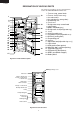
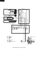
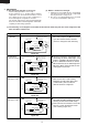
WIRING DIAGRAM
Be sure to replace the electrical parts with specified ones for maintaining the safety and performance of the set.
Figure W-1. Wiring Diagram
Compress
or
Starting relay(P.T.C relay)
C
M
A
Lamp
(BR)
(BK)
(SB)
(OR)
(W)
Protector
(BL)
(R)
(GY)
(Y)
Door Switch
Fan Motor
Defrost Heater
Defrost Thermo.
Thermo.Fuse
F-Thermostat
P
lug / Cord
Defrost Timer
L
FM
TM
CONNECTED IN TERMINAL BOX
CONNECTOR
GY
BR
OR
Y
R
P
BL
BK
SB
G-Y
W
: GRAY
: BROWN (live)
: ORANGE
: YELLOW
: RED
: PINK
: BLUE(neutral)
: BLACK
: SKY-BLUE
: GREEN-YELLOW (earth)
: WHITE