SJ-A20S/B21S/A24S/B25S/A28A/B27S/A31S/A34S-SL SERVICE MANUAL No.S9902SJ22FTVTT Refrigerator-freezer MODELS Ag SJ-F230G SJ-F230G SJ-F230G SJ-A28S-SL SJ-B27S-SL SJ-A20S-SL SJ-B21S-SL SJ-A24S-SL SJ-B25S-SL SJ-A28S-SL SJ-B27S-SL SJ-A31S-SL SJ-A34S-SL DESTINATION T Refrigerant; HFC-134a Refer to "HFC-134a COOLING UNIT" Service Manual for handling this refrigerant. CONTENTS CHAPTER 1. SPECIFICATION [1] SJ-A20S/B21S/A24S/B25S/A28S/B27S........ 2-1 [2] SJ-A31S/A34S .........................................
!"#$% &'$( &#$) &'$* &#$+ &'$, &#-( &#-) SJD34NSLG CHAPTER 1. SPECIFICATION Service Manual SJ-A20S/B21S/A24S/B25S/A28S/B27S SJ-A20S SJ-A24S SJ-B21S SJ-B25S Type 2-Door Outer dimensions Height 1253mm(49.3") 1389mm(54.7") Width 545mm(21.5") 545mm(21.5") Depth 620mm(24.4") 620mm(24.4") Rate storage volume (Rated volume) 184liter(6.5cu.ft) 212liter(7.5cu.
!"#$% &'$( &#$) &'$* &#$+ &'$, &#-( &#-) SJD34NSLG SJ-A31S/A34S Service Manual SJ-A31S SJ-A34S 2-Door Height 1580mm(62.2") 1700mm(66.9") Width 600mm(23.6") 600mm(23.6") Depth 631mm(24.8") 631mm(24.8") Rated storage volume (Rated volume) 292liter(10.3cu.ft) 313liter(11.1cu.
!"#$% &'$( &#$) &'$* &#$+ &'$, &#-( &#-) SJ26NSL CHAPTER 2. DESIGNATION OFVARIOUS Service PARTSManual [1] EXTERNAL DESCRIPTION The names in parenthesis "[ ]" are the denominations used in the REPLACEMENT PARTS LIST. 1 12 2 3 13 4 14 5 15 6 16 7 17 18 8 19 9 1. Freezer shelf [F-shelf] 2. Freezer temp.control knob 3. Ice cube maker 4. Ice cube box [Ice storage box] 5. Fresh room 6. Refrigerator temp.control knob 7. Light [Lamp] 8. Refrigerator shelf [ R-shelf (plastic) : SJ-A20S/B21S; 1 pc.
!"#$% &'$( &#$) &'$* &#$+ &'$, &#-( &#-) [2] CONSTRUCTIONS Mark: Cold air flow Fan motor F-temp. control knob Def-thermistor Evaporator Fuse ass'y Defrost heater Deodorizing unit R-temp.
!"#$% &'$( &#$) &'$* &#$+ &'$, &#-( &#-) SJD26LVSL CHAPTER 3. DIMENTIONS [1] OUTER DIMENTIONS AND CLEARANCE 1. SJ-A20S/B21S 60 628.5 610 60 60 545 443.5 545 1145 34 4 757.5 1085 1253 9 365 970 (Unit:mm) 2. SJ-A24S/B25S 60 628.5 610 60 60 545 9 443.5 545 1145 34 4 893.
!"#$% &'$( &#$) &'$* &#$+ &'$, &#-( &#-) 3. SJ-A28S/B27S 60 628.5 610 60 60 545 9 515.5 545 1145 34 4 923.5 1085 1491 365 970 (Unit:mm) 4. SJ-A31S 649.5 631 600 9 541.5 600 34 4 986.
!"#$% &'$( &#$) &'$* &#$+ &'$, &#-( &#-) 5. SJ-A34S 649.5 631 600 9 34 4 1106.5 1161 1700 405 1065 [2] INNER DIMENTIONS 1. SJ-A20S/B21S 196 366 154 380 143 107 103 390 45 340 204 66 138 67 55 33 38 391 146 250 107 211 208 253 366 208 417 120 149 371 300 292 321 43 417 80 67 137 363 (Unit:mm) 3–3 1221 541.
!"#$% &'$( &#$) &'$* &#$+ &'$, &#-( &#-) 2. SJ-A24S/B25S 38 55 33 366 66 154 138 45 143 103 390 340 107 67 380 204 196 391 187 91 30 292 271 371 154 120 107 417 86 417 292 434 68 211 208 253 366 208 43 417 214 250 169 180 80 137 67 363 (Unit:mm) 3.
!"#$% &'$( &#$) &'$* &#$+ &'$, &#-( &#-) 4. SJ-A31S 416 67 66 231 66 154 45 92 107 67 111 445 217 68 30 43 472 380 237 91 312 312 330 472 147 180 170 55 33 416 138 204 254 217 530 38 430 430 107 210 120 231 472 217 217 259 430 80 152 67 411 5.
!"#$% &'$( &#$) &'$* &#$+ &'$, &#-( &#-) SJ26NSL CHAPTER 4. LIST OF ELECTRICAL PARTS ITEMS R Thermistor Defrost Thermistor TYPE NAME ― ― RATING DC 5V DC 5V SPECIFICATIONS R0 = 6.4 kΩ, B(0) = 3811 R0 = 6.4 kΩ, B(0) = 3811 Thermo. fuse SF70E Defrost heater ― Fan motor (A20S/B21S/A24S/B25S/ 3R00121 A28S/B27S) 250V 10A 220 - 240V 378Ω Working temp. : 70 °C 140W at 230V (A31S/A34S) 3R00101B AC 220-240V,50Hz ― AC 220-230V,60Hz Door switch SDKNA20101 250V 0.25A 125V 0.
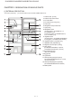
!"#$% &'$( &#$) &'$* &#$+ &'$, &#-( &#-) SJD26LVSL CHAPTER 5. WIRING DIAGRAM [1] WIRING DIAGRAM Be sure to replace the electrical parts with specified ones for maintaining the safety and performance of the set.
!"#$% &'$( &#$) &'$* &#$+ &'$, &#-( &#-) [2] ELECTRIC ACCESSORIES LAYOUT F-LOUVER ASS’Y CABINET FAN MOTOR FM LEAD EV COVER HARNESS FL ASS’Y FUSE DEF-THERMISTOR DEF-HEATER R-CBOX-K PWB LAMP R-THERMISTOR DOOR SWITCH TERMINAL COVER PROTECTOR COMPRESSOR RUN CAP.
!"#$% &'$( &#$) &'$* &#$+ &'$, &#-( &#-) [ ] PRECAUTIONS FOR USING LEAD-FREE SOLDER 1. Employing lead-free solder The PWB of this model employs lead-free solder. This is indicated by the "LF" symbol printed on the PWB and in the service manual. The suffix letter indicates the alloy type of the solder. Example: Indicates lead-free solder of tin, silver and copper 2. Using lead-free wire solder When repairing a PWB with the "LF" symbol, only lead-free solder should be used.
!"#$% &'$( &#$) &'$* &#$+ &'$, &#-( &#-) SJ431NSL CHAPTER 6. FAILURE DIAGNOSIS Service Manual [1] OUTLINE OF CONTROL 1. ON/OFF Control of Compressor When the plug of refrigerator is connected, the compressor will start automatically and run for approximately 5 minutes. After then, ON/OFF of the compressor will be controlled depend on the temperature detected by the R-thermistor. During 6 minutes after the compressor stops, it will not start regardless of the detected temperature by R-thermistor.. 2.
!"#$% &'$( &#$) &'$* &#$+ &'$, &#-( &#-) [3] RE-SETTING OF MICROCOMPUTER AT POWER FAILURE • At the power failure for over 0.1 second, the control of the microcomputer will be reset. When the power is re-supplied, the temperature of R-thermistor will be detected again and ON/OFF of the compressor will be decided. • At the momentary power failure (less than 0.1 second), the protector of the compressor might work due to the high load to the compressor for restarting.
!"#$% &'$( &#$) &'$* &#$+ &'$, &#-( &#-) [5] CONVERSION TABLE Conversion Table between R-thermistor and Def-thermistor Temperature and Resistance Value Temperature (°C) -25 -24 -23 -22 -21 -20 -19 -18 -17 -16 -15 -14 -13 -12 Resistance Value (kΩ) 26.1 24.54 23.08 21.72 20.46 19.27 18.16 17.13 16.16 15.25 14.4 13.6 12.85 12.15 Temperature (°C) -11 -10 -9 -8 -7 -6 -5 -4 -3 -2 -1 0 1 2 Resistance Value (kΩ) 11.49 10.88 10.3 9.75 9.24 8.76 8.3 7.87 7.47 7.09 6.74 6.4 6.08 5.
!"#$% &'$( &#$) &'$* &#$+ &'$, &#-( &#-) [6] CIRCUIT DIAGRAM OF MAIN PWB 6–4
!"#$% &'$( &#$) &'$* &#$+ &'$, &#-( &#-) SJD26LVSL CHAPTER 7. FUNCTIONS [1] ADJUSTABLE TEMPERATURE CONTROL 1. Temperature control 1) FREEZER COMPARTMENT The FREEZER TEMP. CONTROL regulates the quantity of cold air to the freezer. "MAX" setting directs more cold air to the freezer compartment. (making the freezer compartment colder) "MIN" setting directs less cold air to the freezer compartment. (making the freezer compartment less colder) KNOB SETTING MAX PURPOSE For making ice rapidly of fast freezing.
!"#$% &'$( &#$) &'$* &#$+ &'$, &#-( &#-) 3. Temp. control system Freezer Temp. Control Knob The FREEZER TEMP. CONTROL regulates the quantity of cold air to the freezer. MAX setting directs more cold air to the freezer compartment. (making the freezer compartment colder) MIN setting directs less cold air to the freezer compartment.
!"#$% &'$( &#$) &'$* &#$+ &'$, &#-( &#-) SJD26LVSL CHAPTER 8. ASSEMBLING PROCEDURES OF MAIN PARTS AND CAUTIONS CAUTION: DISCONNECT THE UNIT FROM THE POWER SUPPLY BEFORE ANY REPAIRING. [1] F-LOUVER ASS'Y (SJ-A20S/B21S/A24S/B25S/A28S/B27S) 1. Fan motor ass'y Propeller fan 90 Fan motor holder a Fan clamp Lead EV-cover Slit area Motor cushion U-sealer handle Fan motor holder b Motor cushion Fan motor U-sealer handle Figure A-1 1. Stick U-sealer handle to Fan motor holder b (Fig. A-2). 2.
!"#$% &'$( &#$) &'$* &#$+ &'$, &#-( &#-) 2. EV-cover ass'y 1. Bind Fuse ass'y with L-band c. Then wind glass cloth tape (W25 x L50mm ) to lead wire of Fuse ass'y (Figure A-5). L-band c Fuse ass’y Glass cloth tape W25xL50 Figure A-5 2. Stick EVC-sealer a to square hole of EV-cover. 3. Set Fan motor ass'y to EV-cover. Then Fix with 2 tapping screw(Figure A-6) . 4. Set Fuse ass'y to EV-cover then stick aluminum tape (W39 x L35mm) and EV-cover al to EV-cover. 5.
!"#$% &'$( &#$) &'$* &#$+ &'$, &#-( &#-) 3. F - louver ass'y 1. Set F-louver to front side of EV-cover with double face tape (W15xL45mm.). 2. Insert F-control knob to F-louver. Then set to front side of EV-cover. 3. Stick EVC-sealer c to bottom of F-louver ass'y. Lead EV-cover more than 3.5mm. more than 3.5mm.
!"#$% &'$( &#$) &'$* &#$+ &'$, &#-( &#-) [2] F-LOUVER ASS'Y (SJ-A31S/A34S) 1. Fan motor ass'y Fan motor holder b Tapping screw Motor cushion Motor cushion Fan motor U-sealer handle Fan motor holder a Tapping screw Slit area Fan clamp U-sealer handle Lead EV-cover BROWN RED Propeller fan 100 Figure A-1 1. Stick U-sealer handle to Fan motor holder a (Fig. A-2). 2. Insert the terminal of Lead EV-cover to Fan motor (Fig. A-3). 3.
!"#$% &'$( &#$) &'$* &#$+ &'$, &#-( &#-) 2. EV-cover ass'y 1. Bind Fuse ass'y with L-band c. Then wind glass cloth tape (W25 x L50mm ) to lead wire of Fuse ass'y (Figure A-5). L-band c Fuse ass’y Glass cloth tape W25xL50 Figure A-5 2. Stick EVC-sealer a to square hole of EV-cover. 3. Set Fan motor ass'y to EV-cover. Then Fix with 3 tapping screw(Figure A-6) . 4. Set Fuse ass'y to EV-cover then stick aluminum tape (W39 x L35mm) and EV-cover al to EV-cover. 5.
!"#$% &'$( &#$) &'$* &#$+ &'$, &#-( &#-) 3. F - louver ass'y 1. Set F-louver to front side of EV-cover with double face tape (W15xL45mm.). 2. Insert F-control knob to F-louver. Then set to front side of EV-cover. 3. Stick EVC-sealer c to bottom of F-louver ass'y. Lead EV-cover more than 3.5mm. more than 3.5mm.
!"#$% &'$( &#$) &'$* &#$+ &'$, &#-( &#-) [3] R CONTROL COV. ASS'Y R-Control knob R-C Box cover Control label Lamp Figure A-10 1. Insert Lead R-Thermistor to Lead R-C Box. 2. Inset Lead R-C box to PWB L ass'y. 3. Assemble the PWB L ass’y with PWB holder A and then assemble the PWB holder A with PWB holder B. 4. Stick the R-control AL on PWB holder A/B ass’y.
!"#$% &'$( &#$) &'$* &#$+ &'$, &#-( &#-) 5. Assemble Lamp with R-C Box cover then fix with 2 tapping screw. 6. Stick Knob sealer on R-C Box cover and then insert Knob joint to R-C Box cover. 7. Assemble the PWB ass'y with R-C Box cover. And place the R-Thermistor on the groove of R-C Box cover. 8. Insert Lead R-C Box to Lamp. R-C Box cover R-C Box cover Knob joint Knob sealer Figure A-12 PWB holder Lamp R-Thermistor R-C Box cover Figure A-13 9. Insert R-Control knob to R-C Box cover. 10.
!"#$% &'$( &#$) &'$* &#$+ &'$, &#-( &#-) [4] HOW TO REPLACE THE LAMP 1. Remove the Light cover. 2. Remove the 2 screw, and pull the Lamp out. Screw 3. Insert the new Lamp to the connector, and fix with 2 screws. 4. Set the Light cover.
!"#$% &'$( &#$) &'$* &#$+ &'$, &#-( &#-) [5] DEFROST HEATER 2. Replacement of Def. heater. 1. Taking-out Evaporator 1. Remove the aluminium tape on Heater support to take it off from the food liner. 1. Take-out Fan louver ass’y. 2. Raise the protrusion part of Heater support. Then remove Heater cover. 2. Take-out E.V cover ass’y. Protrusion parts Evaporator Heater support Food liner convex part Figure A-15 Heater cover 3.
!"#$% &'$( &#$) &'$* &#$+ &'$, &#-( &#-) 3. Installing of Evaporator 4. Replace Def. heater ass’y with new one. 1. Install Evaporator as shown in Figure.A-15 in the reverse order of Figure.A-16. Heater cover 2. Correct the deformed fin. NOTE: 1.When installing Evaporator, take care not to deform significantly and break the pipes. Def. heater ass'y 2.Take care not to damage the lead wires and hurt yourself by the fin of Evaporator. 3.You shouldn’t touch Defrost Heater with your bare hand.
!"#$% &'$( &#$) &'$* &#$+ &'$, &#-( &#-) SJ26NSL CHAPTER 9. COOLING UNIT Service Manual [1] COOLING UNIT NOTE: The iron pipe is partly used of this refrigerator. Please note the following points when brazing the iron pipe. • Brazing material should be silver brazing rod. (To be equivalent with BAg-20 or BAg-7) • Flux should be FB3A type. (It should be non-chlorine type). • Place an iron plate or cloth on the base frame to prevent the flux fall.
!"#$% &'$( &#$) &'$* &#$+ &'$, &#-( &#-) [2] LOCATION 1. Location 1 Dryer Capillary tube Dryer connector Hot pipe Charge pipe Evaporator Charge pipe L Back condenser * Suction pipe S.P Discharge connector P connector Compressor Mark shows Cu brazing points Mark shows Ag brazing points 2. Location 2 Discharge P. connector to Back condenser * Back condenser to Hot pipe Pinch Point D.P. butyl Pinch point Dryer connector to Dryer Hot pipe to Dryer connector Charge pipe to Dryer S.