Cover SJ300 Series Inverter Instruction Manual • Three-phase Input • Three-phase Input U.S. Version Models Manual Number: NB613XJ September 2006 200V Class 400V Class European Version Models After reading this manual, keep it handy for future reference. Hitachi Industrial Equipment Systems Co., Ltd.
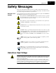
SJ300 Inverter Safety Messages For the best results with the SJ300 Series inverter, carefully read this manual and all of the warning labels attached to the inverter before installing and operating it, and follow the instructions exactly. Keep this manual handy for quick reference. Definitions and Symbols A safety instruction (message) includes a hazard alert symbol and a signal word, WARNING or CAUTION. Each signal word has the following meaning: This symbol indicates HIGH VOLTAGE.
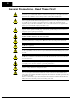
ii General Precautions - Read These First! WARNING: This equipment should be installed, adjusted, and serviced by qualified electrical maintenance personnel familiar with the construction and operation of the equipment and the hazards involved. Failure to observe this precaution could result in bodily injury. WARNING: The user is responsible for ensuring that all driven machinery, drive train mechanism not supplied by Hitachi Industrial Equipment Systems Co., Ltd.
SJ300 Inverter CAUTION: a) Motor must be connected to protective ground via low resistive path (< 0.1Ω) b) Any motor used must be of a suitable rating. c) Motors may have hazardous moving parts. In this event suitable protection must be provided. CAUTION: Alarm connection may contain hazardous live voltage even when inverter is disconnected. When removing the front cover for maintenance or inspection, confirm that incoming power for alarm connection is completely disconnected.
iv Index to Warnings and Cautions in This Manual Installation—Cautions for Mounting Procedures CAUTION: Be sure to install the unit on flame-resistant material such as a steel plate. Otherwise, there is the danger of fire. ............... 2–6 CAUTION: Be sure not to place any flammable materials near the inverter. Otherwise, there is the danger of fire. ...............
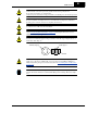
SJ300 Inverter HIGH VOLTAGE: Be sure to ground the unit. Otherwise, there is a danger of electric shock and/or fire. ............. 2–13 HIGH VOLTAGE: Wiring work shall be carried out only by qualified personnel. Otherwise, there is a danger of electric shock and/or fire. ............. 2–13 HIGH VOLTAGE: Implement wiring after checking that the power supply is OFF. Otherwise, you may incur electric shock and/or fire. .............
vi CAUTION: Fasten the screws with the specified fastening torque in the table below. Check for any loosening of screws. Otherwise, there is the danger of fire. ............. 2–16 CAUTION: Remarks for using ground fault interrupter breakers in the main power supply: Adjustable frequency inverters with CE-filters (RFI-filter) and shielded (screened) motor cables have a higher leakage current toward Earth GND.
SJ300 Inverter Warnings for Operations and Monitoring WARNING: Be sure to turn ON the input power supply only after closing the front case. While the inverter is energized, be sure not to open the front case. Otherwise, there is the danger of electric shock. ............... 4–3 WARNING: Be sure not to operate electrical equipment with wet hands. Otherwise, there is the danger of electric shock. ...............
viii Cautions for Operations and Monitoring CAUTION: The heat sink fins will have a high temperature. Be careful not to touch them. Otherwise, there is the danger of getting burned. ............... 4–2 CAUTION: The operation of the inverter can be easily changed from low speed to high speed. Be sure check the capability and limitations of the motor and machine before operating the inverter. Otherwise, it may cause injury to personnel. ...............
SJ300 Inverter WARNING: The screws that retain the capacitor bank assembly are part of the electrical circuit of the high-voltage internal DC bus. Be sure that all power has been disconnected from the inverter, and that you have waited at least 5 minutes before accessing the terminals or screws. Be sure the charge lamp is extinguished. Otherwise, there is the danger of electrocution to personnel. .............
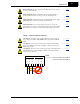
x CAUTION: Do not insert leading power factor capacitors or surge absorbers between the output terminals of the inverter and motor. Ground fault interrupter Power Input Surge absorber Inverter GFI R, S, T L1, L2, L3 Motor U, V, W GND lug Leading power factor capacitor CAUTION: Be sure to connect the grounding terminal to earth ground. CAUTION: When inspecting the unit, be sure to wait five minutes after tuning OFF the power supply before opening the cover.
SJ300 Inverter CAUTION: MOTOR TERMINAL VOLTAGE SURGE SUPPRESSION FILTER (For 400 V CLASS Inverters) In a system using an inverter with the voltage control PWM system, a voltage surge caused by the cable constants such as the cable length (especially when the distance between the motor and inverter is 10 m or more) and cabling method may occur at the motor terminals. A dedicated filter of the 400 V class for suppressing this voltage surge is available. Be sure to install a filter in this situation.
xii UL® Cautions, Warnings, and Instructions Wiring Warnings for Electrical Practices and Wire Sizes The Cautions, Warnings, and instructions in this section summarize the procedures necessary to ensure an inverter installation complies with Underwriters Laboratories® guidelines. WARNING: “Use 60/75°C Cu wire only” or equivalent. WARNING: “Open Type Equipment.” For models SJ300–750H to SJ300–1500H.
xiii SJ300 Inverter Input Voltage 400V Motor Output 400V Inverter Model HP kW 1 0.75 SJ300-007HFU/E 2 1.5 3 Torque Wire Size Range (AWG) ft-lbs (N-m) 20 1.1 1.5 SJ300-015HFU/E 18 1.1 1.5 2.2 SJ300-022HFU/E 16 1.1 1.5 5 4.0 SJ300-040HFU/E 14 1.1 1.5 7.5 5.5 SJ300-055HFU/E 12 1.8 2.5 10 7.5 SJ300-075HFU/E 10 1.8 2.5 15 11 SJ300-110HFU/E 8 3.6 4.9 20 15 SJ300-150HFU/E 6 3.6 4.9 25 18.5 SJ300-185HFU/E 6 3.6 4.9 30 22 SJ300-220HFU/E 4 3.6 4.
xiv Fuse and Circuit Breaker Sizes Input Voltage 200V Motor Output HP kW 1/2 0.4 The inverter’s input power wiring must include UL Listed, dual-element, 600V fuses, or UL Listed, inverse-time, 600V circuit breakers. 200V Inverter Model SJ300-004LFU Ampere Rating for Fuse or Breaker Motor Output Input Voltage HP 10 1 400V Inverter Model kW Ampere Rating for Fuse or Breaker 0.75 SJ300-007HFU/E 10 1 0.75 SJ300-007LFU 10 2 1.5 SJ300-015HFU/E 10 2 1.5 SJ300-015LFU 10 3 2.
SJ300 Inverter Table of Contents Safety Messages Hazardous High Voltage General Precautions - Read These First! Index to Warnings and Cautions in This Manual General Warnings and Cautions UL® Cautions, Warnings, and Instructions i ii iv ix xii Table of Contents Revisions Contact Information xvii xviii Chapter 1: Getting Started Introduction SJ300 Inverter Specifications Introduction to Variable-Frequency Drives Frequently Asked Questions 1–2 1–6 1–13 1–17 Chapter 2: Inverter Mounting and Installation
xvi Chapter 5: Inverter System Accessories Introduction Component Descriptions Dynamic Braking 5–2 5–3 5–6 Chapter 6: Troubleshooting and Maintenance Troubleshooting Monitoring Trip Events, History, & Conditions Restoring Factory Default Settings Maintenance and Inspection Warranty 6–2 6–5 6–9 6–10 6–18 Appendix A: Glossary and Bibliography Glossary Bibliography A–2 A–6 Appendix B: Serial Communications Introduction Communications Protocol Communications Reference Information B–2 B–5 B–17 Appendix C
SJ300 Inverter Revisions Revision History Table Date of Issue Operation Manual No.
xviii Contact Information Hitachi America, Ltd. Power and Industrial Division 50 Prospect Avenue Tarrytown, NY 10591 U.S.A. Phone: +1-914-631-0600 Fax: +1-914-631-3672 Hitachi Australia Ltd. Level 3, 82 Waterloo Road North Ryde, N.S.W. 2113 Australia Phone: +61-2-9888-4100 Fax: +61-2-9888-4188 Hitachi Europe GmbH Am Seestern 18 D-40547 Düsseldorf Germany Phone: +49-211-5283-0 Fax: +49-211-5283-649 Hitachi Industrial Equipment Systems Co., Ltd.
Getting Started In This Chapter.... 1 page — Introduction ....................................................................................... 2 — SJ300 Inverter Specifications ........................................................... 6 — Introduction to Variable-Frequency Drives...................................... 13 — Frequently Asked Questions...........................................................
Geting Started 1–2 Introduction Introduction Main Features Congratulations on your purchase of an SJ300 Series Hitachi inverter! This inverter drive features state-of-the-art circuitry and components to provide high performance. The housing footprint is exceptionally small, given the size of the corresponding motor. The Hitachi SJ300 product line includes more than twenty inverter models to cover motor sizes from 1/2 horsepower to 200 horsepower, in either 230 VAC or 480 VAC power input versions.
SJ300 Inverter The SJ300 Series inverters have a detachable keypad (called a digital operator) on the front panel of the housing. The particular keypad that comes with the inverter depends on the country or continent corresponding to the particular model number. The standard digital operators occupy just part of the keypad recess in the panel. Therefore, the inverter comes with a snap-in panel filler plate that mounts below the keypad as shown.
Geting Started 1–4 Introduction Removable Components The SJ300 Series inverters are designed for long life and ease of service. Several components are removable as shown below, aiding installation or parts replacement. Details on how and when to remove these parts are in the referenced chapters.
SJ300 Inverter 1–5 Getting Started Specifications The Hitachi SJ300 inverters have product specifiLabel and Agency cations labels located on the front and the right side of the housing, as pictured to the right. Be Approvals sure to verify that the specifications on the labels match your power source, motor, and application safety requirements.
Geting Started 1–6 SJ300 Inverter Specifications SJ300 Inverter Specifications Tables for 200V class inverters Note that “General Specifications” on page 1–9 covers all SJ300 inverters, followed by footnotes for all specifications tables. The 200V models in the upper table below (1/2 to 15 hp) include internal dynamic braking units (see “Dynamic Braking” on page 5–6). Item 200V Class Specifications SJ300, 200V models, U.S.
1–7 SJ300 Inverter Note that “General Specifications” on page 1–9 covers all SJ300 inverters, followed by footnotes for all specifications tables. The 400V models in the upper table below (1 to 15 hp) include internal dynamic braking units (see “Dynamic Braking” on page 5–6). Item SJ300 inverters, 400V models 400V Class Specifications U.S. version European ver.
1–8 SJ300 Inverter Specifications Geting Started Tables for 400V class inverters, continued... Item SJ300 inverters, 400V models 400V Class Specifications U.S. version 750HFU 900HFU 1100HFU — 1500HFU European ver. 750HFE 900HFE 1100HFE 1320HFE — 100 125 150 175 200 Applicable motor size *2 HP kW Rated capacity (400 / 480V) kVA 75 90 110 132 150 103.2 / 123.8 121.9 / 146.3 150.3 / 180.4 180.1 / 216.1 180.1 / 216.
SJ300 Inverter General Specifications 1–9 The following table (continued on next page) applies to all SJ300 inverter models. General Specifications Protective enclosure *1, *11 IP20 (NEMA 1) Control method Line-to-line sine wave pulse-width modulation (PWM) control Output frequency range *4 0.1 to 400 Hz Frequency accuracy Digital command: ± 0.01% of the maximum frequency Analog command: ± 0.2% (25°C ± 10°C) Frequency setting resolution Digital: ± 0.01 Hz; Analog: (max.
1–10 SJ300 Inverter Specifications Geting Started Item General Specifications Other user-settable parameters V/F free-setting (up to 7 points), freq. upper/lower limit, freq. jump, accel/decel curve selection, manual torque boost value and freq.
SJ300 Inverter Use the following derating curves to help determine the optimal carrier frequency setting for your inverter, and to find the output current derating. Be sure to use the proper curve for your particular SJ300 inverter model number. SJ300 1.5 to 22 kW at 50 deg. C ambient 004 to 150L % of Drive’s Rated Amps 100% 95% 90% 85% 185L 80% 75% 70% 220L 65% 0.5 2 4 6 8 10 12 14 15 Carrier Frequency (kHz) SJ300 30 to 55 kW at 50 deg.
1–12 SJ300 Inverter Specifications Geting Started Derating curves, continued... SJ300 30 to 55 kW at 50 deg. C ambient, continued 015 to 185H % of Drive’s Rated Amps 100% 95% 370H 90% 450H 85% 80% 220H 75% 300H 70% 65% 60% 550H 0.5 2 4 6 8 10 12 14 15 Carrier Frequency (kHz) SJ300 75 to 150 kW at 50 deg. C ambient % of Drive’s Rated Amps 100% 95% 750H 90% 85% 80% 900H 75% 70% 1100H 65% 1320H 1500H 60% 0.
SJ300 Inverter 1–13 The Purpose of Motor Speed Control for Industry Hitachi inverters provide accurate speed control for 3-phase AC induction motors. You connect AC power to the inverter, and connect the inverter to the motor.
Geting Started 1–14 Introduction to Variable-Frequency Drives vector is related to motor flux current, and the other to motor torque current. The ability to separately control these two vectors is what allows the SJ300 to deliver extraordinary lowspeed performance and speed control accuracy. Inverter Input and The Hitachi SJ300 Series of inverters includes two sub-groups: the 200V class and the 400V class inverters.
1–15 SJ300 Inverter Much of this manual is devoted to describing how to use inverter functions and how to configure inverter parameters. The inverter is microprocessor-controlled, and has many independent functions. The microprocessor has an on-board EEPROM for parameter storage. The inverter’s front panel keypad provides access to all functions and parameters, which you can access through other devices as well. The general name for all these devices is the digital operator, or digital operator panel.
Geting Started 1–16 Introduction to Variable-Frequency Drives Acceleration and deceleration settings specify the time required to go from a stop to maximum frequency (or visa versa). The Speed resulting slope (speed change divided by time) is the acceleration or deceleration. An increase in output frequency uses the acceleration slope, while a decrease uses the deceleration slope. The accel or decel time a particular speed change depends on the starting and ending frequencies.
SJ300 Inverter 1–17 Q. What is the main advantage in using an inverter to drive a motor, compared to alternative solutions? A. Q. The term “inverter” is a little confusing, since we also use “drive” and “amplifier” to describe the electronic unit that controls a motor. What does “inverter” mean? A. Q. A specific inverter model is set at the factory to work across a voltage range particular to the destination country for that model.
1–18 Frequently Asked Questions Q. What type of motor is compatible with the Hitachi inverters? Geting Started A. Motor type – It must be a three phase AC induction motor. Use an inverter-grade motor that has 800V insulation for 200V class inverters, or 1600V insulation for 400V class. Motor size – In practice, it’s better to find the right size motor for your application; then look for the inverter to match the motor.
Inverter Mounting and Installation In This Chapter.... 2 page — Orientation to Inverter Features ........................................................ 2 — Basic System Description ................................................................. 5 — Step-by-Step Basic Installation ......................................................... 6 — Powerup Test .................................................................................. 21 — Using the Front Panel Keypad .................................
2–2 Orientation to Inverter Features Orientation to Inverter Features Unpacking and Inspection Please take a few moments to unpack your new SJ300 inverter and perform these steps: 1. Look for any damage that may have occurred during shipping. 2. Verify the contents of the box include: Inverter Mounting and Installation a. One SJ300 inverter b. One Instruction Manual (supplied by printed book for –FU/–FR models, supplied on CR-ROM for –FE models) c. One SJ300 Quick Reference Guide d.
SJ300 Inverter Press here and slide cover downward Inverter Mounting and Installation 2. Second-level access - First, ensure no power source of any kind is connected to the inverter. If power has been connected, wait five minutes after powerdown and verify the Charge Lamp indicator is OFF to proceed. Then locate the recessed retention screw at the bottom of the main front panel. Use a small Phillips screwdriver to remove the screw.
Inverter Mounting and Installation 2–4 Orientation to Inverter Features 3. Third-level access - The SJ300 provides for field installation of interface circuits. These circuits are on expansion cards, to be installed in the expansion bay. To access the expansion bay, you will need to remove the upper front panel. Use the latch to release the digital operator (the panel filler plate may remain). Remove the two retention screws the bottom corners of the upper front panel.
SJ300 Inverter 2–5 Basic System Description A motor control system will obviously include a motor and inverter, as well as a breaker or fuses for safety. If you are connecting a motor to the inverter on a test bench just to get started, that’s all you may need for now. But a system can also have a variety of additional components. Some can be for noise suppression, while others may enhance the inverter’s braking performance.
2–6 Step-by-Step Basic Installation Step-by-Step Basic Installation This section will guide you through the following basic steps of installation: 1. Study the warnings associated with mounting the inverter. 2. Select a suitable mounting location. Inverter Mounting and Installation NOTE: If the installation is in an EU country, study the EMC installation guidelines in Appendix D. 3. Cover the inverter’s top ventilation openings to prevent debris from falling inside. 4.
SJ300 Inverter 2 Ensure Adequate Ventilation 2–7 Step 2: To summarize the caution messages—you will need to find a solid, non-flammable, vertical surface that is in a relatively clean and dry environment. In order to ensure enough room for air circulation around the inverter to aid in cooling, maintain the specified clearance around the inverter specified in the diagram. Clear area 10 cm (3.94”) minimum Exhaust Inverter Mounting and Installation 5 cm (1.97”) minimum 5 cm (1.
Step-by-Step Basic Installation 150(5.91) 130(5.12) Exhaust 6(0.24) 10(0.39) 21(0.83) 130(5.12) 108(4.25) 40 (1.57) 40 (1.57) 241(9.49) 255(10.04) 295(11.61) 10(0.39) 2 - φ 6(0.24) 108(4.25) 3 - φ 28(1.10) Wiring hole (knockout) Air intake 64.5(2.54) 75(2.95) Conduit box 7(0.28) 143(5.63) SJ300 -075LFU/HFE, HFU -110LFU/HFE, HFU 10.5(0.41) Exhaust 210(8.27) 189(7.44) 2 - φ 7(0.28) 246(9.69) Model 3 - φ 44(1.73) Air intake 80(3.15) Wiring hole (knockout) Conduit box 7(0.28) 82(3.
SJ300 Inverter 2–9 Dimensional drawings, continued... 10.5(0.41) 250(9.84) 229(9.02) Exhaust 2 - φ 7(0.28) 104(4.09) Conduit box 190(7.48) 3 - φ 44(1.73) Wiring hole (knockout) Air intake 244(9.61) 9.5(0.37) 83(3.27) 86(3.39) 104(4.09) 229(9.02) 204(8.03) 147(5.79) 147(5.79) 537(21.14) 7(0.28) 10.5(0.41) 23(0.91) Inverter Mounting and Installation 376(14.80) 390(15.35) Model SJ300 -150LFU/HFE, HFU -185LFU/HFE, HFU -220LFU/HFE, HFU 15 (0.59) 22.5(0.89) 310(12.20) 265(10.
2–10 Step-by-Step Basic Installation Dimensional drawings, continued... Model 45(1.77) 390(15.35) 300(11.81) Exhaust 2 - φ 12(0.47) 185(7.28) 185(7.28) Inverter Mounting and Installation 705(27.76) 520(20.47) 520(20.47) 550(21.65) SJ300 -370LFU/HFE, HFU -450LFU/HFE, HFU -550HFE, HFU 2 - 12(0.47) 300(11.81) 45(1.77) 387(15.23) 1.5(0.06) Air intake 250(9.84) 154 90 (6.06) (3.54) 90(3.54) Optional adapter for NEMA1 rating 2 - φ 12(0.47) 2(0.08) 670(26.38) 700(27.56) 15 (0.
SJ300 Inverter 2–11 Dimensional drawings, continued... Exhaust 2 - φ 12(0.47) Model 2 - 12(0.47) 300(11.81) 390(15.34) 185(7.28) 670(26.38) 700(27.56) Inverter Mounting and Installation SJ300 -750HFE, HFU -900HFE, HFU Air intake 270(10.63) 90(3.
2–12 Step-by-Step Basic Installation Dimensional drawings, continued... 2 - φ 12(0.47) Exhaust Model 710(27.95) 740(29.13) 380(14.96) 480(18.90) 190(7.48) 2 - 12(0.47) Air intake 104(4.09) 270(10.
SJ300 Inverter 5 Prepare for Wiring 2–13 Step 5: The wiring enters the inverter through the entry/exit plate as shown to the right. The rubber grommets have a solid, thin membrane, so that unused ones continue to seal the opening. To create an opening, use a sharp knife and carefully cut an “X” in the center of the grommet as shown. Be especially careful to avoid cutting into the thick outer ring, so that the wiring will have a cushion from contacting the metal plate.
2–14 Step-by-Step Basic Installation Determining Wire This section includes tables for 200V class and 400V class inverters (on the next page). The following notes will help you read the tables in this section: and Fuse Sizes • Locate the row corresponding to the motor size and particular inverter in your application. The maximum motor current determines the recommended wire sizes.
2–15 SJ300 Inverter Determining wire and fuse sizes, continued... Wiring *1 Motor Output Power Lines *3 400V Inverter Models Chassis Ground mm2 SJ300–007HFU/E 20 1.25 10A 10A 16 1.5 SJ300–015HFU/E 18 2 10A 10A 3 2.2 SJ300–022HFU/E 16 2 10A 10A HP kW 1 0.75 2 Breaker AWG, AWG, ( GFI rec. UL type) *2 mm2 AWG mm2 14 1.25 20 1.25 16 14 1.25 18 2 16 14 1.25 16 2 5 4.0 SJ300–040HFU/E 14 2 15A 15A 16 14 1.25 14 2 7.5 5.
2–16 Step-by-Step Basic Installation Terminal Dimensions and Torque Specs The following tables list the screw size of terminal and recommended torque for tightening for each of the SJ300 inverter models (400V models are on the next page). Inverter Mounting and Installation CAUTION: Fasten the screws with the specified fastening torque in the table below. Check for any loosening of screws. Otherwise, there is the danger of fire.
2–17 SJ300 Inverter Terminal dimensions and torque specs, continued... Input Voltage 400V Inverter Models Screw size of terminal Ring lug connector *1 Torque (AWG-bolt) (mm2–bolt) ft-lbs (N-m) M4 20–#10 1.25–4 1.1 1.5 SJ300-015HFU/E M4 14–#10 2–4 1.1 1.5 2.2 SJ300-022HFU/E M4 14–#10 2–4 1.1 1.5 HP kW 1 0.75 SJ300-007HFU/E 2 1.5 3 5 4.0 SJ300-040HFU/E M4 14–#10 2–4 1.1 1.5 7.5 5.5 SJ300-055HFU/E M5 14–#12 2–5 1.8 2.5 10 7.5 SJ300-075HFU/E M5 10–#12 3.
2–18 Step-by-Step Basic Installation 6 Inverter Mounting and Installation Wire the Inverter Input to a Supply Step 6: In this step, you will connect wiring to the input of the inverter. All models have the same power connector terminals [R(L1)], [S(L2)], and [T(L3)] for three-phase input. The three phases may be connected in any order, as they are isolated from chassis ground and do not determine motor direction of rotation.
SJ300 Inverter 2–19 NOTE: An inverter powered by a portable or emergency diesel power generator may result in a distorted power waveform, overheating the generator. In general, the generator capacity should be at least five times that of the inverter (kVA). CAUTION: Be sure that the input voltage matches the inverter specifications: • Three phase 200 to 240V 50/60Hz • Three phase 380 to 480V 50/60Hz CAUTION: Be sure not to connect an AC power supply to the output terminals.
2–20 Step-by-Step Basic Installation 7 Wire the Inverter Output to Motor Step 7: The process of motor selection is beyond the scope of this manual. However, it must be a three-phase AC induction motor. It should also come with a chassis ground lug. If the motor does not have three power input leads, stop the installation and verify the motor type. Other guidelines for wiring the motor include: • Use an inverter-grade motor for maximum motor life (1600V insulation).
SJ300 Inverter 2–21 Powerup Test 9 Perform the Powerup Test Step 9: After wiring the inverter and motor, you’re ready to do a powerup test. The procedure that follows is designed for the first-time use of the drive. Please verify the following conditions before conducting the powerup test: • You have followed all the steps in this chapter up to this step. • The inverter is new, and is securely mounted to a non-flammable vertical surface • The inverter is connected to a power source and motor.
2–22 Powerup Test Inverter Mounting and Installation CAUTION: If you operate a motor at a frequency higher than the inverter standard default setting (50Hz/60Hz), be sure to check the motor and machine specifications with the respective manufacturer. Only operate the motor at elevated frequencies after getting their approval. Otherwise, there is the danger of equipment damage and/or injury to personnel. CAUTION: Check the following before and during the powerup test.
SJ300 Inverter 2–23 Using the Front Panel Keypad Front Panel Introduction Please take a moment to familiarize yourself with the keypad layout shown in the figure below. Parameter Display Alarm LED Run/Stop LED POWER ALARM HITACHI RUN HZ 5 0.0 PRG V A kW % Run Key Enable LED STOP RESET RUN MIN Run Key FUNC.
2–24 Using the Front Panel Keypad • Function Key – This key is used to navigate through the lists of parameters and functions for setting and monitoring parameter values. Inverter Mounting and Installation • Up/Down ( 1 , 2 ) Keys – Use these keys alternately to move up or down the lists of parameter and functions shown in the display, and increment/decrement values.
SJ300 Inverter 2–25 Keypad The SJ300 Series inverter drives have many programmable functions and parameters. Chapter 3 Navigational Map will cover these in detail, but you need to access just a few items to perform the powerup test. The menu structure makes use of function codes and parameter codes to allow programming and monitoring with only a 4-digit display and a few keys and LEDs. So, it is important to become familiar with the basic navigational map of parameters and functions in the diagram below.
2–26 Using the Front Panel Keypad Selecting Functions and Editing Parameters In order to run the motor for the powerup test, this section will show how to: • select the inverter’s maximum output frequency to the motor • select the keypad potentiometer as the source of motor speed command • select the keypad as the source of the RUN command • set the number of poles for the motor Inverter Mounting and Installation • enable the RUN command The following series of programming tables are designed for succe
SJ300 Inverter 2–27 Select the Potentiometer for Speed Command - The motor speed may be controlled from the following sources: • Potentiometer on front panel keypad (if present) • Control terminals • Remote panel Then follow the steps in the table below to select the potentiometer for the speed command (the table resumes action from the end of the previous table). Press the 2 key twice. Press the FUNC. key. Press the 2 key. Press the STR key. Display A001 01 00 A001 Func.
2–28 Using the Front Panel Keypad Configure the Inverter for the Number of Motor Poles- The number of magnetic poles of a motor is determined by the motor’s internal winding arrangement. The specifications label on the motor usually indicates its number of poles. For proper operation, verify the parameter setting matches the motor poles. Many industrial motors have four poles, corresponding to the default setting in the inverter.
SJ300 Inverter Monitoring Parameters with the Display After using the keypad for parameter editing, it’s a good idea to switch the inverter from Program Mode to Monitor Mode. This will turn out the PRG LED, and the Hertz, Volt, Ampere, or % LED indicates the display units. POWER ALARM HITACHI RUN HZ 5 0.0 PRG 2–29 V A kW % STOP RESET RUN MIN MAX STR For the powerup test, monitor the motor speed indirectly by viewing the inverter’s output frequency.
2–30 Using the Front Panel Keypad 10 Step 10: Reading this section will help you make some useful observations when first running the motor. Error Codes - If the inverter displays an error code (LED format is “E X X”), see “Monitoring Powerup Test Observations and Trip Events, History, & Conditions” on page 6–5 to interpret and clear the error. Summary Acceleration and Deceleration - The SJ300 inverter has programmable acceleration and Inverter Mounting and Installation deceleration values.
Configuring Drive Parameters In This Chapter.... 3 page — Choosing a Programming Device ..................................................... 2 — Using Keypad Devices...................................................................... 3 — “D” Group: Monitoring Functions ...................................................... 6 — “F” Group: Main Profile Parameters.................................................. 8 — “A” Group: Standard Functions .........................................................
3–2 Choosing a Programming Device Choosing a Programming Device Introduction Hitachi variable frequency drives (inverters) use the latest electronics technology for getting the right AC waveform to the motor at the right time. The benefits are many, including energy savings and higher machine output or productivity. The flexibility required to handle a broad range of applications has required ever more configurable options and parameters—inverters are now a complex industrial automation component.
SJ300 Inverter 3–3 Using Keypad Devices Inverter Front Panel Keypad The SJ300 Series inverter front keypad contains all the elements for both monitoring and programming parameters. The keypad layout (OPE–SRE) is shown below. All other programming devices for the inverter have a similar key arrangement and function. Parameter Display Alarm LED Run/Stop LED Program/Monitor LED Power LED POWER ALARM HITACHI RUN HZ 5 0.
3–4 Using Keypad Devices Keypad Whether you use the keypad on the inverter or the read-write copy unit, each navigates the same Navigational Map way. The diagram below shows the basic navigational map of parameters and functions. Monitor Mode Program Mode Select Function Display Data Select Parameter Edit Parameter 1 d 090 D002–D090 0.00 1 U01 2 1 2 FUNC. 2 d 001 P049 2 1 d 001 U001 FUNC. STR Configuring Drive Parameters FUNC. FUNC.
3–5 SJ300 Inverter Operational Modes The RUN and PGM LEDs tell just part of the story; Run Mode and Program Modes are independent modes, not opposite modes. In the state diagram to the right, Run alternates with Stop, and Program Mode alternates with Monitor Mode. This is a very important ability, for it shows that a technician can approach a running machine and change some parameters without shutting down the machine.
3–6 “D” Group: Monitoring Functions “D” Group: Monitoring Functions Parameter Monitoring Functions You can access important system parameter values with the “D” Group monitoring functions, whether the inverter is in Run Mode or Stop Mode. After selecting the function code number for the parameter you want to monitor, press the Function key once to show the value on the display. In Functions D005 and D006 the intelligent terminals use individual segments of the display to show ON/OFF status.
SJ300 Inverter “D” Function Func. Code Name Description Run Range Mode and Units Edit SRW Display D014 Power monitor 0.0 to 999.9 — kW D016 Cumulative operation RUN time monitor Displays total time the inverter has been in RUN mode in hours. Range is 0 to 9999 / 1000 to 9999/ 100 to 999 (10,000 to 99,900) hrs. — hours RUN 0000000hr D017 Cumulative power-on time monitor Displays total time the inverter has had input power (ON) in hours. Range is: 0 to 9999 / 100.0 to 999.
3–8 “F” Group: Main Profile Parameters “F” Group: Main Profile Parameters Configuring Drive Parameters The basic frequency (speed) profile is defined by parameters contained in the Output “F” Group as shown to the right. The F002 F003 output frequency is set in Hz, but accel- frequency eration and deceleration are specified F001 seconds (the time to ramp from zero to maximum frequency, or from maximum frequency to zero).
3–9 SJ300 Inverter “A” Group: Standard Functions Basic Parameter Settings These settings affect the most fundamental behavior of the inverter—the outputs to the motor. The frequency of the inverter’s AC output determines the motor speed. You may select from three different sources for the reference speed. During application development you may prefer using the potentiometer, but you may switch to an external source (control terminal setting) in the finished application, for example.
3–10 “A” Group: Standard Functions “A” Function Configuring Drive Parameters Func. Code Name Description Run Mode Edit Defaults Lo Hi –FE (EU) –FU (US) –FR (JP) Units SRW Display A203 Base frequency setting, 2nd motor Settable from 30 Hz to the maximum frequency ✘✘ 50. 60. 60. Hz >A203 2F-BASE F 0060Hz A303 Base frequency setting, 3rd motor Settable from 30 Hz to the maximum frequency ✘✘ 50. 60. 60.
SJ300 Inverter Analog Input Settings 3–11 The inverter has the capability to accept external analog inputs that can command the output frequency to the motor. Signals including voltage input (0 to +10V) at terminal [O], bipolar input (-10 to +10V) at terminal [O2], and current input (4 to 20mA) at terminal [OI] are available. Terminal [L] serves as signal ground for the three analog inputs. The analog input settings adjust the curve characteristics between the analog input and the frequency output.
3–12 “A” Group: Standard Functions “A” Function Configuring Drive Parameters Func. Code Name Description Run Mode Edit Defaults Lo Hi –FE (EU) –FU (US) –FR (JP) Units SRW Display A005 [AT] selection Two options; select codes: 00 Select between [O] and [OI] at [AT] 01 Select between [O] and [O2] at [AT] ✘✘ 00 00 00 — >A005 AT SELECT A006 [O2] selection Four options; select codes: 00 No summing, [O2] and [OI] 01 Sum of [O2] and [OI], neg.
SJ300 Inverter Multi-speed and Jog Frequency Settings 3–13 The SJ300 inverter has the capability to store and output up to 16 preset frequencies to the motor (A020 to A035). As in traditional motion terminology, we call this multi-speed profile capability. These preset frequencies are selected by means of digital inputs to the inverter. The inverter applies the current acceleration or deceleration setting to change from the current output frequency to the new one.
3–14 “A” Group: Standard Functions Torque Control Algorithms The inverter generates the motor output according to the V/f algorithm or the sensorless vector control algorithm. Parameter A044 selects the inverter torque control algorithm for generating the frequency output, as shown in the diagram to the right (A244 and A344 for 2nd and 3rd motors, respectively). The factory default is 00 (constant torque V/f control).
SJ300 Inverter 3–15 c. After reaching the base frequency, the characteristic maintains a constant output voltage for higher frequencies. Using parameter A045 you can modify the voltage gain of the inverter. This is specified as a percentage of the full-scale setting AVR (Automatic Voltage Regulation) in parameter A082. The gain can be set from 20% to 100%. It must be adjusted in accordance with the motor specifications.
3–16 “A” Group: Standard Functions The V/f free-setting endpoint f7/V7 parameters must stay within the more basic inverter limits in order for the specified free-setting characteristic curve to be achieved. For example, the inverter cannot output a higher voltage than the input voltage or the AVR setting voltage (Automatic Voltage Regulation), set by parameter A082. The graph to the right shows how the inverter input voltage would clip (limit) the characteristic curve if exceeded.
SJ300 Inverter “A” Function Func. Code Name Description Run Mode Edit 3–17 Defaults Lo Hi –FE (EU) –FU (US) –FR (JP) Units SRW Display Can boost starting torque between 0 and 20% above normal V/f curve, from 0 to 1/2 base frequency ✔✔ 1.0 1.0 1.0 — >A042 V-Boost Code 01.0% A242 Manual torque boost value, 2nd motor Can boost starting torque between 0 and 20% above normal V/f curve, from 0 to 1/2 base frequency ✔✔ 1.0 1.0 1.0 — >A242 2V-Boost Code 01.
3–18 “A” Group: Standard Functions DC Braking Settings The DC braking feature can provide additional stopping torque when compared to a normal deceleration to a stop. It can also ensure the motor and load are stopped before acceleration. Configuring Drive Parameters When decelerating – DC braking is particularly useful at low speeds when normal deceleration torque is minimal.
3–19 SJ300 Inverter “A” Function Func. Code Name Run Mode Edit Description Defaults Lo Hi –FE (EU) –FU (US) –FR (JP) Units SRW Display A051 DC braking enable Two options; select codes: 00 Disable 01 Enable ✘✔ 00 00 00 — >A051 DCB Mode A052 DC braking frequency setting The frequency at which DC braking activates during decel. Range is 0.00 to 60.00 Hz ✘✔ 0.50 0.50 0.50 Hz >A052 DCB F 00.
3–20 “A” Group: Standard Functions FrequencyFrequency Limits – Upper and lower related Functions limits can be imposed on the inverter Output frequency output frequency. These limits will apply regardless of the source of the speed reference. You can configure the lower frequency limit to be greater than zero as shown in the graph to the right. The upper limit must not exceed the rating of the motor or capability of the machinery.
SJ300 Inverter “A” Function Func. Code Run Mode Edit Defaults Units SRW Display 0.00 Hz >A063 JUMP F1 0000.00Hz >A065 JUMP F2 0000.00Hz >A067 JUMP F3 0000.00Hz 0.50 Hz >A064 JUMP W1 00.50Hz >A066 JUMP W2 00.50Hz >A068 JUMP W3 00.50Hz Lo Hi –FE (EU) –FU (US) –FR (JP) A063 Jump (center) frequency Up to 3 output frequencies A065 setting can be defined for the output A067 to jump past to avoid motor resonances (center frequency) Range is 0.00 to 400.0 Hz ✘✔ 0.00 0.
3–22 “A” Group: Standard Functions PID Control When enabled, the built-in PID loop calculates an ideal inverter output value to cause a loop feedback process variable (PV) to move closer in value to the setpoint (SP). The current frequency command serves as the SP. The PID loop algorithm will read the analog input for the process variable (you specify either current or voltage input) and calculate the output.
SJ300 Inverter Automatic Voltage Regulation (AVR) Function The automatic voltage regulation (AVR) feature keeps the inverter output voltage at a relatively constant amplitude during power input fluctuations. This can be useful if the installation is subject to input voltage disturbances. However, the inverter cannot boost its motor output to a voltage higher than the power input voltage. If you enable this feature, be sure to select the proper voltage class setting for your motor. “A” Function Func.
3–24 “A” Group: Standard Functions Optimal Accel/Decel Operation, continued... The acceleration time is controlled to maintain output current below the level set by the Overload Restriction Function if enabled (Parameters B021/B024, B022/B025, and B023/ B026). If Overload Restriction is not enabled, then the current limit used is 150% of the inverter’s rated output current.
SJ300 Inverter “A” Function Func. Code Name Description Run Mode Edit 3–25 Defaults Lo Hi –FE (EU) –FU (US) –FR (JP) Units SRW Display Duration of 2nd segment of acceleration, range is: 0.01 to 3600 sec. ✔✔ 15.0 15.0 15.0 sec. >A092 ACCEL TIME2 0015.00s A292 Acceleration (2) time setting, 2nd motor Duration of 2nd segment of acceleration, 2nd motor, range is: 0.01 to 3600 sec. ✔✔ 15.0 15.0 15.0 sec. >A292 2ACCEL TIME2 0015.
3–26 “A” Group: Standard Functions Accel/Decel Characteristics Standard (default) acceleration and deceleration is linear with time. The inverter CPU can also calculate other curves shown in the graphs below. The sigmoid, U-shape, and reverse U-shape curves are useful for favoring the load characteristics in particular applications. Curve settings for acceleration and deceleration are independently selected via parameters A097 and A098, respectively.
SJ300 Inverter 3–27 The acceleration and deceleration curves can deviate from a straight line to a varying degree. Parameters A131 and A132 control the amount of deviation for the acceleration and deceleration curves respectively. The following graphs show intermediate output frequency points as a percentage of the target frequency, for 25%, 50%, and 75% acceleration time intervals. Output frequency % of target Output frequency % of target Output frequency % of target 100 99.6 93.8 87.5 68.4 64.
3–28 “A” Group: Standard Functions Additional Analog Input Settings The parameters in the following table adjust the input characteristics of the analog inputs. When using the inputs to command the inverter output frequency, these parameters adjust the starting and ending ranges for the voltage or current, as well as the output frequency range. Related characteristic diagrams are located in “Analog Input Settings” on page 3–11. “A” Function Configuring Drive Parameters Func.
3–29 SJ300 Inverter “B” Group: Fine-Tuning Functions The “B” Group of functions and parameters adjust some of the more subtle but useful aspects of motor control and system configuration. Automatic The restart mode determines how the inverter will resume operation after a fault causes a trip Restart Mode and event. The four options provide advantages for various situations.
3–30 “B” Group: Fine-Tuning Functions “B” Function Configuring Drive Parameters Func. Code Name Description Run Mode Edit Defaults Lo Hi –FE (EU) –FU (US) –FR (JP) Units SRW Display B002 Allowable undervoltage power failure time The amount of time a power input under-voltage can occur without tripping the power failure alarm. If under-voltage exists longer than this time, the inverter trips, even if the restart mode is selected. If it exists less than this time retry will be attempted.
3–31 SJ300 Inverter The torque developed in a motor is directly proportional to the current in the windings, which is also proportional to the heat generated (and temperature, over time). Therefore, you must set the thermal overload threshold in terms of current (amperes) with parameter B012. The range is 50% to 120% of the rated current for each inverter model. If the current exceeds the level you specify, the inverter will trip and log an event (error E5) in the history table.
3–32 “B” Group: Fine-Tuning Functions Constant Torque Characteristic – Selecting the constant torque characteristic for the example motor gives the curves below. At 2.5 Hz, the output current is reduced by a factor of 0.9 for given trip times. Trip current reduction factor x 1.0 Trip time (s) 60 x 0.9 x 0.8 0.5 0 Hz 2.5 5 0 A 60 47.8 62.1 82.8 Configuring Drive Parameters 104% 135% 180% Reduced trip current at 2.
SJ300 Inverter 3–33 Any intelligent output terminal may be programmed to indicate a thermal warning [THM]. Parameter C061 determines the warning threshold. Please see “Thermal Warning Signal” on page 4–55 for more details. “B” Function Func.
3–34 “B” Group: Fine-Tuning Functions Configuring Drive Parameters Overload Restriction If the inverter’s output current exceeds a restriction area preset current level you specify during Motor B022 acceleration or constant speed, the Current overload restriction feature automati0 cally reduces the output frequency to t restrict the overload. This feature does not generate an alarm or trip event.
SJ300 Inverter “B” Function Func. Code Name Description Run Mode Edit Lo Hi 3–35 Defaults –FE (EU) –FU (US) –FR (JP) B025 Overload restriction setting (2) Sets the level for overload restriction (2), between 50% and 200% of the rated current of the inverter, setting resolution is 1% of rated current ✘✔ rated current times 1.50 B026 Deceleration rate at overload restriction (2) Sets the deceleration rate (2) when inverter detects overload, range is 0.1 to 30.0, resolution is 0.1. ✘✔ 1.00 1.
3–36 “B” Group: Fine-Tuning Functions Software Lock Mode The software lock function keeps personnel from accidentally changing parameters in the inverter memory. Use B031 to select from various protection levels. Configuring Drive Parameters The table below lists all combinations of B031 option codes and the Run ON/OFF state of the [SFT] input. Each Check ✔ or Ex ✘ indicates Mode whether the corresponding parameter(s) can be edited.
SJ300 Inverter Miscellaneous Settings The miscellaneous settings include scaling factors, initialization modes, and others. This section covers some of the most important settings you may need to configure. “B” Function Func. Code 3–37 Name Run Mode Edit Description Defaults Lo Hi –FE (EU) –FU (US) –FR (JP) Units SRW Display B034 Run/power-on warning time Range is 0 to 65,530 hours ✘✔ 0. 0. 0. hrs.
Configuring Drive Parameters 3–38 “B” Group: Fine-Tuning Functions Function Code Data A044, A244 02 B100 – B113 Control methods A051 01 A052 – A059 DC braking A071 01 A072 – A076, C044 PID function A094 01 A095 – A096 2-stage adjustable frequency A294 01 A0295 – A296 B013, B213, B313 02 B015 – B020 Electric thermal characteristic B021 01, 02 B022, B023 Overload restriction B024 01, 02 B025, B026 Overload restriction 2 B095 01, 02 B090 – B096 Dynamic braking function 0
SJ300 Inverter Function Code C021 – C025, C026 Data H202 C042, C043 Frequency arrival signal 03 C040, C041 Overload advance notice 07 C055 – C058 Over-torque 21 C063 Zero-speed detection signal C045, C046 Frequency arrival signal 26 C011 Overload advance notice 2 00 H020 – H024 Motor constant 01, 02 H030 – H034 Motor constant (auto-tuning) 00 H220 – H224 Motor constant 01, 02 H023 – H0234 Motor constant (auto-tuning) P011 – P023, P025 – P027 Expansion card function 01 “B”
3–40 “B” Group: Fine-Tuning Functions “B” Function Func. Code Name Description B046 Reverse Run protection enable Prohibits reverse motor rotation. Two option codes: 00 Disable 01 Enable Run Mode Edit Defaults Lo Hi –FE (EU) –FU (US) –FR (JP) ✘✔ 00 00 00 SRW Display Units — >b046 LIMIT PREV OFF Controlled Deceleration at Power Loss – When enabled, this feature permits the inverter to control final motor deceleration upon loss of inverter input power.
SJ300 Inverter 3–41 Miscellaneous functions, continued... B083: Carrier frequency adjustment – The internal switching frequency of the inverter circuitry (also called the chopper frequency). It is called the carrier frequency because the lower AC output frequency of the inverter “rides” the carrier. The faint, high-pitched sound you hear when the inverter is in Run Mode is characteristic of switching power supplies in general.
3–42 “B” Group: Fine-Tuning Functions “B” Function Configuring Drive Parameters Func. Code Run Mode Edit Defaults Units SRW Display 00 — >b085 INITIAL SELECT USA 1.0 1.0 — >b086 F-CONV Gain 001.
3–43 SJ300 Inverter B091/B088: Stop Mode / Restart Mode Configuration – You can configure how the inverter performs a standard stop (each time Run FWD and REV signals turn OFF). Setting B091 determines whether the inverter will control the deceleration, or whether it will perform a free-run stop (coast to a stop). When using the free-run stop selection, it is imperative to also configure how you want the inverter to resume control of motor speed.
3–44 “B” Group: Fine-Tuning Functions “B” Function Configuring Drive Parameters Func. Code Name Description Run Mode Edit Defaults Lo Hi –FE (EU) –FU (US) –FR (JP) Units SRW Display B090 Dynamic braking usage ratio Selects the braking duty cycle for the dynamic braking resistor (total brake % ON-time per 100 sec. interval). Range is 0.0 to 100.0% 0%Dynamic braking disabled >0% Enabled, per value ✘✔ 00 00 00 — >b090 BRD %ED 000.
SJ300 Inverter Free-setting V/f Pattern 3–45 The free-setting V/f inverter mode of operation uses voltage and frequency parameter pairs to define seven points on a V/f graph. This provides a way to define a multi-segment V/f curve that best suits your application. The frequency settings do require that F1 ≤ F2 ≤ F3 ≤ F4 ≤ F5 ≤ F6 ≤ F7; their values must have this ascending order relationship.
3–46 “B” Group: Fine-Tuning Functions External Brake Control The brake control function in the inverter controls external braking used in systems such as elevators. The purpose of this function is to ensure the inverter is powering the motor before releasing external brakes that would permit the load to move or coast. This function requires the configuration and wiring of intelligent input and output terminals. See “External Brake Control Function” on page 4–39 for more information.
SJ300 Inverter 3–47 “C” Group: Intelligent Terminal Functions The eight input terminals [1], [2], [3], [4], [5], [6], [7], and [8] can be configured for any of 44 different functions. The next two tables show how to configure the eight terminals. The inputs are logical, in that they are either OFF or ON. We define these states as OFF=0, and ON=1. The inverter comes with default options for the eight terminals. These default settings are initially unique, each one having its own setting.
3–48 “C” Group: Intelligent Terminal Functions The input logic convention is programmable for each of the six inputs. Most inputs default to normally open (active high), but you can select normally closed (active low) in order to invert the sense of the logic. “C” Function Configuring Drive Parameters Func.
SJ300 Inverter Intelligent Input Terminal Overview 3–49 Each of the eight intelligent terminals may be assigned any of the options in the following table. When you program one of the option codes for terminal assignments C001 to C008, the respective terminal assumes the function role of that option code. The terminal functions have a symbol or abbreviation, which we use to label a terminal using that function. For example the “Reverse Run” command is [RV].
3–50 “C” Group: Intelligent Terminal Functions Input Function Summary Table Option Code Terminal Symbol 13 USP Configuring Drive Parameters 14 15 16 17 18 20 21 22 23 CS SFT AT SET3 RS STA STP F/R PID Function Name Unattended Start Protection Description ON On powerup, the inverter will not resume a Run command (mostly used in the US) OFF On powerup, the inverter will resume a RUN command that was active before power loss ON OFF-to-ON transition signals the inverter that the m
SJ300 Inverter 3–51 Input Function Summary Table Option Code Terminal Symbol 24 PIDC 26 27 29 31 32 33 34 35 36 37 38 UP DWN UDC OPE SF1 SF2 SF3 SF4 SF5 SF6 SF7 PID Reset Description ON Resets the PID loop controller. The main consequence is that the integrator sum is forced to zero.
3–52 “C” Group: Intelligent Terminal Functions Input Function Summary Table Option Code Terminal Symbol 39 OLR 40 Configuring Drive Parameters 41 42 43 44 45 46 47 48 no TL TRQ1 TRQ2 PPI BOK ORT LAC PCLR STAT — Function Name Overload restriction Description ON Selects current overload parameter set 2 (B024, B025, B026) OFF Selects current overload parameter set 1 (B021, B022, B023) ON Enables torque limit feature OFF Disables all torque limit sources.
SJ300 Inverter Output Terminal Configuration The inverter provides configuration for logic (discrete) and analog outputs, shown in the table below. “C” Function Func.
3–54 “C” Group: Intelligent Terminal Functions “C” Function Func.
SJ300 Inverter 3–55 Output Function Summary Table Option Code Terminal Symbol 06 FA3 07 08 10 11 12 13 19 20 21 22 IP UV TRQ RNT ONT THM BRK BER ZS DSE Frequency arrival type 3 – at frequency Over-torque signal Instantaneous power failure signal Under-voltage signal In torque limit Operation time over Plug-in time over Thermal alarm signal Brake release signal Brake error signal Zero speed detect Speed deviation maximum Description ON when output to motor is at the FA
3–56 “C” Group: Intelligent Terminal Functions Output Function Summary Table Option Code Terminal Symbol 23 POK 24 Configuring Drive Parameters 25 26 Function Name Description Positioning completion ON FA4 Frequency arrival type 4 – over-frequency (2) FA5 Frequency arrival type 5 – at frequency (2) OL2 Overload notice advance signal (2) when the load position is at the target OFF when the load position is not yet at the target ON when output to motor is at or above the FA threshold 2
3–57 SJ300 Inverter Output Function Adjustment Parameters The following parameters work in conjunction with the intelligent output function, when configured. The overload level parameter (C041) sets the motor current level at which the overload signal [OL] turns ON. The range of settings is from 0% to 200% of the rated current for the inverter.
3–58 “C” Group: Intelligent Terminal Functions “C” Function Configuring Drive Parameters Func. Code Name Description Run Mode Edit Defaults Lo Hi –FE (EU) –FU (US) –FR (JP) Units SRW Display C044 PID deviation level setting Sets the PID loop error threshold |SP - PV| (absolute value) to trigger intelligent output [OD]. Range is 0.0 to 100%, resolution is 0.1% ✘✔ 3.0 3.0 3.0 % >C044 PID LEVEL 003.0% C045 Frequency arrival setting for acceleration (2) Range is 0.0 to 99.99 / 100.
SJ300 Inverter 3–59 Serial The following table configures the communications port of the SJ300 inverter. You can have up Communications to thirty-two devices on the serial communications network. The inverters are slaves and the computer or digital operator is the master. Thus, all inverters on the serial connection must use the same baud rate, data length, parity, and stop bits. However, each device on the serial network must have a unique node address.
3–60 “C” Group: Intelligent Terminal Functions Analog Signal Calibration Settings The functions in the following table configure the signals for the analog output terminals. Note that these settings do not change the current/voltage or sink/source characteristics – only the zero and span (scaling) of the signals. NOTE: See additional settings for analog calibration: Parameter B080 [AM] Terminal Analog Meter Adjustment (gain), parameter B081 [FM] Terminal Analog Meter Adjustment (gain).
SJ300 Inverter Miscellaneous Functions The following table contains miscellaneous functions not in other function groups. “C” Function Func. Code 3–61 Name Description Run Mode Edit Defaults Lo Hi –FE (EU) –FU (US) –FR (JP) Units SRW Display Two option codes: 00 No display 01 Display ✘✔ 00 00 00 — >C091 INITIAL DEBG OFF C101 Up/Down memory mode selection Controls speed setpoint for the inverter after power cycle.
3–62 “H” Group: Motor Constants Functions “H” Group: Motor Constants Functions Introduction Configuring Drive Parameters The “H” Group parameters configure the inverter for the motor characteristics. You must manually set H003 and H004 values to match the motor. Most of the remaining parameters are related to vector control, and are in use only when function A044 is set for one of the vector control modes as shown in the diagram.
SJ300 Inverter “H” Function Func. Code Name Description Run Mode Edit Lo Hi 3–63 Defaults –FE (EU) –FU (US) –FR (JP) Units SRW Display kW >H203 2AUX K 003.70kW Select 0.2 to 75.0kW for models up to –550xxx, 0.2 to 160.
3–64 “H” Group: Motor Constants Functions “H” Function Configuring Drive Parameters Func. Code Name Description Run Mode Edit Lo Hi Defaults –FE (EU) –FU (US) –FR (JP) Units SRW Display — >H224 2AUX J 000.055 H224 Motor constant J, 2nd motor Ratio (unit-less), range is 1.
SJ300 Inverter 3–65 “P” Group: Expansion Card Functions The two (optional) expansion cards for the SJ300 have associated configuration data. The following table defines the functions and their value ranges. Please refer to the expansion card manual for more details. “P” Function Func.
3–66 “P” Group: Expansion Card Functions “P” Function Configuring Drive Parameters Func. Code Name Description Run Mode Edit Defaults Lo Hi –FE (EU) –FU (US) –FR (JP) Units SRW Display P022 Feed-forward gain setting Range is 0.00 top 99.99 / 100.0 ✘✔ 0.00 0.00 0.00 — >P022 FEEDBACK FFWG 000.00 P023 Position loop gain setting Range is 0.00 to 99.99 / 100.0 ✘✔ 0.50 0.50 0.50 — >P023 FEEDBACK G 000.
SJ300 Inverter 3–67 “U” Group: User-selectable Menu Functions The user-selectable menu functions allow you to configure (select) any twelve of the other functions in the inverter and place them together in a convenient list. This feature provides quick access for the most-used functions needed for your application. Each U Group function can serve as a pointer to any of the other parameters.
3–68 Programming Error Codes Programming Error Codes The SJ300 inverter operator keypad displays a special code (begins with the character) to indicate a programming error. Programming errors exist when one parameter conflicts with the meaningful range permitted by related parameter(s). Note that particular real-time frequency (speed) input levels can cause a conflict in some situations. After a conflict exists, the error code will appear on the display, or you can view it later with D090 in Monitor Mode.
SJ300 Inverter Programming Error Code Parameter out of bounds Code Description Boundary defined by... <, > Code Description B112 Free-setting V/f frequency (7) A061 / A261 Frequency upper limit setting; 1st, 2nd motor > 092 292 A062 / A262 Frequency lower limit setting; 1st, 2nd motor > 095 295 F001, A020 / A220 Output frequency setting, Multi-speed freq. setting; 1st, 2nd motor > 096 A021 to A035 Multi-speed freq.
Operations and Monitoring In This Chapter.... 4 page — Introduction ....................................................................................... 2 — Optional Controlled Decel and Alarm at Power Loss........................ 4 — Connecting to PLCs and Other Devices ........................................... 7 — Using Intelligent Input Terminals ..................................................... 11 — Using Intelligent Output Terminals ..................................................
4–2 Introduction Introduction The previous material in Chapter 3 gave a reference listing of all the programmable functions of the inverter. We suggest that you first scan through the listing of inverter functions to gain a general familiarity. This chapter will build on that knowledge in the following ways: 1. Related functions – Some parameters interact with or depend on the settings in other functions.
SJ300 Inverter Warnings for Operating Procedures 4–3 Before continuing, please read the following Warning messages. WARNING: Be sure to turn ON the input power supply only after closing the front case. While the inverter is energized, be sure not to open the front case. Otherwise, there is the danger of electric shock. WARNING: Be sure not to operate electrical equipment with wet hands. Otherwise, there is the danger of electric shock.
4–4 Optional Controlled Decel and Alarm at Power Loss Optional Controlled Decel and Alarm at Power Loss With the default SJ300 inverter configuration, a sudden power loss will cause the inverter to shut down immediately. If running at the time, the motor and load will coast to a stop. And without power, the inverter’s alarm output will not activate. This default performance may be fine for applications with loads such as fans and pumps.
SJ300 Inverter 4–5 Follow the steps to implement the wiring change shown in the previous diagram. 1. Remove the 2-wire jumper J51 (terminals [R0] and [T0] to connector J51). 2. Procure several inches of multi-strand 20 AWG (0.5mm2) or slightly heavier wire. 3. Connect a wire to terminal [R0] that is long enough to connect to terminal [P] (do not connect to [P] yet). 4. Connect a wire to terminal [T0] that is long enough to connect to terminal [N] (do not connect to [N] yet). 5.
4–6 Optional Controlled Decel and Alarm at Power Loss The timing diagram below shows a power loss scenario and the related parameter settings. During the controlled deceleration the inverter itself acts as a load to decelerate the motor. With either a high-inertia load or a short deceleration time (or both), it is possible that the inverter impedance will not be low enough to continue linear deceleration and avoid an over-voltage condition on the DC bus.
4–7 SJ300 Inverter Connecting to PLCs and Other Devices Hitachi inverters (drives) are useful in many types of applications. During installation, the inverter keypad (or other programming device) will facilitate the initial configuration. After installation, the inverter will generally receive its control commands through the control logic terminals or serial interface from another controlling device.
4–8 Connecting to PLCs and Other Devices Example Wiring Diagram The schematic diagram below provides a general example of logic connector wiring, in addition to basic power and motor wiring covered in Chapter 2. The goal of this chapter is to help you determine the proper connections for the various terminals shown below for your specific application needs.
SJ300 Inverter 4–9 Specifications of The control logic connector board is removable for wiring convenience as shown below (first, Control and Logic remove two retaining screws). The small connector to the left is for serial communications.
4–10 Connecting to PLCs and Other Devices Terminal Listing Use the following table to locate pages for intelligent input and output material in this chapter. Operations and Monitoring Intelligent INPUTS Symbol Code Name Intelligent OUTPUTS Page Symbol Code Name Page RV 01 Reverse Run/Stop 4–12 RUN 00 Run signal 4–43 CF1 02 Multi-speed select, Bit 0 (LSB) 4–13 FA1 01 4–44 CF2 03 Multi-speed select, Bit 1 4–13 Freq.
4–11 SJ300 Inverter Using Intelligent Input Terminals Intelligent terminals [1], [2], [3], [4], [5], [6], [7], and [8] are identical, programmable inputs for general use. The input circuits can use the inverter’s internal (isolated) +24V field supply (P24) to power the inputs. The input circuits connect internally to [PLC] as a common point. To use the internal supply to power the inputs, use the jumper as shown.
4–12 Using Intelligent Input Terminals Wiring Diagram Conventions The input wiring diagrams in this chapter are examples only. Default and non-default input terminal assignments are noted throughout; your particular assignments may be different. The wiring diagrams show the –xFU/–xFR model default [P24]–[PLC] jumper position (U.S./Jpn versions), as shown below on the left. The common (return) for inputs is [CM1] in this case.
4–13 SJ300 Inverter Multi-Speed Select The inverter can store up to 16 different fixed target frequencies (speeds) in parameters A020 to A035. Binary inputs select the speed through four of the intelligent terminals configured as binary-encoded inputs CF1 to CF4 per the table. These can be any of the eight inputs, and in any order. You can use fewer inputs if you need eight or fewer speeds.
4–14 Using Intelligent Input Terminals Opt.
SJ300 Inverter 4–15 The Bit Operation method of speed control uses up to seven intelligent inputs to select from up to eight speeds. Since the all-switches-OFF combination selects the first speed, you only need N-1 switches to select N speeds. With Bit Operation speed control, only one input is normally active at a time. If multiple switches are ON, the lower numbered input takes precedence (determines the speed). The table and figure below show how the input combinations work.
4–16 Using Intelligent Input Terminals Jogging Command The Jog input [JG] is used to command the motor to rotate slowly in small increments for manual operation. The speed is limited to 10 Hz. The frequency for the jogging operation is set by parameter A038. Jogging does not use an acceleration ramp. Therefore setting the jogging frequency A038 too high will cause inverter tripping. [JG] [FW] [RV] A038 A jog command may arrive while the motor Output t is running.
SJ300 Inverter External Signal for DC Injection Braking When the terminal [DB] is turned ON, the DC braking [DB] feature is enabled. Set the following parameters when the external DC braking terminal is to be used: Scenario 1 [FW, RV] • A053 – DC braking delay time setting. The range 0.0 to 5.0 seconds. [DB] • A054 – DC braking force setting. The range is 0 to 100%. Output frequency t The scenarios to the right help show how DC braking works in various situations. Scenario 2 1.
4–18 Using Intelligent Input Terminals Set Second or Third Motors If you assign the [SET] or [SET3] functions to an intelligent input terminal, you can select between two or three sets of motor parameters. You may assign one or both of these functions. These second and third parameters store alternate sets of motor characteristics. When terminal [SET] or [SET3] is turned ON, the inverter will use the second or third set of parameters accordingly, generating the frequency output to the motor.
4–19 SJ300 Inverter Two-stage When terminal [2CH] is turned ON, the Acceleration and inverter changes the rate of acceleration and deceleration from the initial settings (F002 Deceleration Output frequency and F003) to use the second set of acceleration/deceleration values. When the terminal is turned OFF, the inverter is returned to the original acceleration and deceleration time (F002 acceleration time 1, and F003 deceleration time 1).
4–20 Using Intelligent Input Terminals Free-run Stop When the terminal [FRS] is turned ON, the inverter turns OFF the output and the motor enters the free-run state (coasting). If terminal [FRS] is turned OFF, the output resumes sending power to the motor if the Run command is still active. The free-run stop feature works with other parameters to provide flexibility in stopping and starting motor rotation.
SJ300 Inverter External Trip 4–21 When the terminal [EXT] is turned ON, the inverter enters the trip state, indicates error code E12, and stops the output. This is a general purpose interrupt type feature, and the meaning of the error depends on what you connect to the [EXT] terminal. Even if [EXT] is turned OFF, the inverter remains in the trip state. You must reset the inverter or cycle power to clear the error, returning the inverter to the Stop Mode.
4–22 Using Intelligent Input Terminals Unattended Start If the Run command is already present when power is turned ON, the inverter starts running immediately after powerup. The Unattended Start Protection (USP) function prevents that Protection automatic startup, so that the inverter will not run without outside intervention. When USP is active, there are two ways to reset an alarm and resume running: 1. Turn the Run command OFF, or 2.
SJ300 Inverter Commercial Power Source Switching 4–23 The commercial power source switching function is useful in systems with excessive starting torque requirements. This feature permits the motor to be started “across the line,” sometimes called a bypass configuration. After the motor is running, the inverter takes over to control the speed. This feature can eliminate the need to oversize the inverter, reducing cost.
4–24 Using Intelligent Input Terminals In the previous timing diagram, when the motor has been started across the line, Mg2 is switched OFF and Mg3 is switched ON. With the Forward command to the inverter already ON, the [CS] terminal is switched ON and relay Mg1 contacts close. The inverter will then read the motor RPM (frequency matching). When the [CS] terminal is switched OFF, the inverter applies the Retry wait time before motor restart parameter (B003).
SJ300 Inverter Software Lock 4–25 When the terminal [SFT] is turned ON, the data of all the parameters and functions (except the output frequency, depending on the setting of B031) is locked (prohibited from editing). When the data is locked, the keypad keys cannot edit inverter parameters. To edit parameters again, turn OFF the [SFT] terminal input. Use parameter B031 to select whether the output frequency is excluded from the lock state or is locked as well. Opt.
4–26 Using Intelligent Input Terminals Operations and Monitoring Analog Input Current/Voltage Select The [AT] terminal operates in conjunction with parameter setting A005 to determine the analog input terminals that are enabled for current or voltage input. Setting A006 determines whether the signal will be bipolar, allowing for a reverse direction range. Note that current input signal cannot be bipolar and cannot reverse direction (must use [FW] and [RV] command with current input operation).
4–27 SJ300 Inverter Reset Inverter The [RS] terminal causes the inverter to execute the reset operation. If the inverter is in Trip Mode, the reset cancels the Trip state. When the signal [RS] is turned ON and OFF, the inverter executes the reset operation. The minimum pulse width for [RS] must be 12 ms or greater. The alarm output will be cleared within 30 ms after the onset of the Reset command. 12 ms minimum [RS] approx.
4–28 Using Intelligent Input Terminals Thermistor Thermal Protection Motors that are equipped with a thermistor can be protected from overheating. Input terminal [TH] is dedicated to sense a thermistor resistance. The input can be set up (via B098 and B099) to accept a wide variety of NTC or PTC type thermistors. Use this function to protect the motor from overheating. Opt.
SJ300 Inverter Three-wire Interface Operation 4–29 The 3-wire interface is an industry standard motor control interface. This function uses two inputs for momentary contact start/stop control, and a third for selecting forward or reverse direction. To implement the 3-wire interface, assign 20 [STA] (Start), 21 [STP] (Stop), and 22 [F/R] (Forward/Reverse) to three of the intelligent input terminals. Use momentary contact for Start and Stop.
4–30 Using Intelligent Input Terminals PID ON/OFF and PID Clear The PID loop function is useful for controlling motor speed to achieve constant flow, pressure, temperature, etc. in many process applications. The PID Disable function temporarily suspends PID loop execution via an intelligent input terminal. It overrides the parameter A071 (PID Enable) to stop PID execution and return to normal motor frequency output characteristics. the use of PID Disable on an intelligent input terminal is optional.
SJ300 Inverter Internal Speed Loop Gain Settings 4–31 When sensorless vector control, 0Hz sensorless vector control, or vector control with sensor is selected for the control method, the Control Gain Switching function selects between two sets of gains in the internal speed loop. These gains are used in proportional and integral compensation. Use option code 26 to assign the [CAS] function to an intelligent input terminal. Use option code 43 to select between P and PI control. Opt.
4–32 Using Intelligent Input Terminals The speed control mode is normally proportionalintegral compensation (PI), which attempts to keep the deviation between the actual speed and speed command equal to zero. You can also select proportional (P) control function, which can be used for droop control (i.e. several inverters driving one load). Droop is the speed difference resulting from P control versus PI control at 100% output torque as shown in the graph.
4–33 SJ300 Inverter Remote Control Up and Down Functions The [UP] [DWN] terminal functions can adjust the output frequency for remote control while the motor is running. The acceleration time and deceleration time used with this function is the same as for normal operation ACC1 and DEC1 (2ACC1,2DEC1). The input terminals operate as follows: • Acceleration - When the [UP] contact is turned ON, the output frequency accelerates from the current value.
4–34 Using Intelligent Input Terminals Operations and Monitoring Force Operation from Digital Operator This function permits a digital operator interface to override the Run command source setting (A002) when it is configured for a source other than the operator interface. When the [OPE] terminal is ON and the operator interface gives a Run command, the inverter uses the standard output frequency settings to operate the motor. Opt.
SJ300 Inverter Overload Restriction 4–35 The inverter constantly monitors the motor current during acceleration, deceleration, and constant speed. If the inverter reaches the overload restriction level, it adjusts the output frequency automatically to limit the amount of overload. This function prevents an over-current trip by inertia during rapid acceleration or large changes in load at constant speed. It also attempts to prevent an over-voltage trip on deceleration due to regeneration.
4–36 Using Intelligent Input Terminals The figure below shows the operation during an overload restriction event. The overload restriction level is set by B022 and B025. The overload restriction constant is the time to decelerate to 0Hz from maximum frequency. When this function operates, the acceleration time will be longer than the normal acceleration time.
SJ300 Inverter Torque Limit 4–37 The Torque Limit function limits the motor output torque for sensorless vector control, sensorless vector control 0Hz domain, or vector control with feedback. In the torque limit function, the following operational modes are available (selected by B040): 1. Four-quadrant individual setting mode – This mode sets torque limit in 4 zones, forward driving and regenerating, reverse driving and regenerating. Limits for each quadrant are set with B041 – B044 individually. 2.
4–38 Using Intelligent Input Terminals The 4-quadrant operation mode for torque limiting (B040=00) is illustrated in the figure to the right. The instantaneous torque depends on inverter activity (acceleration, constant speed, or deceleration), as well as the load. These factors determine the operating quadrant at any particular time. The parameters in B041, B042, B043 and B044 determine the amount of torque limiting that the inverter applies.
SJ300 Inverter 4–39 External Brake The External Brake Control function enables the inverter to control external electromechanical Control Function brake systems with a particular safety characteristic. For example, elevator control systems maintain the brake on the load until the drive motor has reached a releasing frequency (point at which the external mechanical brake is released). This ensures that the load does not have an opportunity to begin coasting before the inverter begins driving the motor.
4–40 Using Intelligent Input Terminals Code Function Data or Range Description B123 Brake wait time for stopping 0.00 to 5.00 sec. Sets the time delay after brake confirmation signal [BOK] turns OFF (after [BRK] turns OFF) until decelerating the inverter to 0 Hz B124 Brake wait time for confirmation 0.00 to 5.00 sec. Sets the wait time for [BOK] signal after turn ON/ OFF of [BRK] signal.
SJ300 Inverter Expansion Card Input Signals 4–41 Other inputs listed below require the expansion card SJ-FB Encoder Feedback. Please see the SJ-FB manual for more information. Opt.
4–42 Using Intelligent Output Terminals Using Intelligent Output Terminals The intelligent output terminals are programmable in a similar way to the intelligent input terminals. The inverter has several output functions that you can assign individually to five physical logic outputs. Along with these solid-state outputs, the alarm relay output has type Form C (normally open and normally closed) contacts.
4–43 SJ300 Inverter Run Signal When the [RUN] signal is selected as an intelligent output terminal, the inverter outputs a signal on that terminal when it is in Run Mode. The output logic is active low, and is the open collector type (switch to common). [FW, RV] Motor speed start freq. B82 Run Signal ON t Opt.
4–44 Using Intelligent Output Terminals Frequency Arrival The Frequency Arrival group of outputs help coordinate external systems with the current velocity profile of the inverter. As the name implies, output [FA1] turns ON when the output Signals frequency arrives at the standard set frequency (parameter F001). Outputs [FA2] through [FA5] provide variations on this function for increased flexibility, relying on two programmable accel/ decel thresholds.
SJ300 Inverter Frequency arrival output [FA1] uses the standard output frequency (parameter F001) as the threshold for switching. In the figure to the right, the inverter accelerates to the set output frequency, which serves as the threshold for [FA1]. Parameters Fon and Foff illustrate the hysteresis that prevents output chatter near the threshold value. Output frequency Hz Foff Fon Threshold F001 • Fon is 1% of the max. output frequency 0 t • Foff is 2% of the max.
4–46 Using Intelligent Output Terminals Overload Advance Notice Signal When the output current exceeds a preset value, the [OL] or [OL2] terminal signal turns ON. The parameter C041 (or C111, respectively) sets the overload threshold. The overload detection circuit operates during powered motor operation and during regenerative braking. The output circuits use open-collector transistors, and are active low.
4–47 SJ300 Inverter Output Deviation The PID loop error is defined as the magnitude (absolute value) of the differfor PID Control ence between the Setpoint (target value) and the Process Variable (actual value). When the error magnitude exceeds the preset value for C044, the [OD] terminal signal turns ON. Refer to “PID Loop Operation” on page 4–71. Error (SP-PV) Set value Process variable Setpoint C044 C044 [OD] Signal ON ON t Opt.
4–48 Using Intelligent Output Terminals Alarm Signal The inverter alarm signal is active when a fault has occurred and it is in the Trip Mode (refer to the diagram at right). When the fault is cleared the alarm signal becomes inactive. Run STOP RESET Stop RUN Operations and Monitoring We must make a distinction between the alarm STOP RESET signal AL and the alarm relay contacts [AL0], Fault [AL1] and [AL2].
SJ300 Inverter 4–49 The alarm output terminals operate as shown below (left) by default. The contact logic can be inverted as shown (below right) by using the parameter setting C036. The relay contacts normally open (N.O.) and normally closed (N.O.) convention uses “normal” to mean the inverter has power and is in Run or Stop Mode. The relay contacts switch to the opposite position when it is in Trip Mode or when input power is OFF.
4–50 Using Intelligent Output Terminals Over-torque Signal The Over-torque function [OTQ] turns ON when the estimated value of output torque of motor increases more than the arbitrary level set for the output. Recall that the torque limit function, covered in “Torque Limit” on page 4–37, actually limits the torque during certain operating conditions. Instead, the over-torque output feature only monitors the torque, turning ON output [OTQ] if the torque is above programmable thresholds you set.
SJ300 Inverter Instantaneous Power Failure / Under-voltage Signal 4–51 An instantaneous power failure (complete loss) or under-voltage condition (partial loss) of inverter input voltage can occur without warning. SJ300 Series inverters can be configured to respond to these conditions in different ways. You can select whether the inverter trips or retries (restart attempt) when an instantaneous power failure or under-voltage condition occurs. You can select the retry function with parameter B001.
4–52 Using Intelligent Output Terminals Opt.
SJ300 Inverter 4–53 Examples 3 and 4 relate to configuring the inverter to retry upon power failure. Frequency matching is possible if the inverter frequency is greater than the B007 value.
4–54 Using Intelligent Output Terminals Torque Limit Signal The Torque Limit output [TRQ] works in conjunction with the torque limit function covered in the intelligent input section. The torque limit function limits the motor torque according to the criteria selected by parameter B040. When torque limiting occurs, the [TRQ] output turns ON, then going OFF automatically when the output torque falls below the specified limits. See “Torque Limit” on page 4–37 in the intelligent input section. Opt.
4–55 SJ300 Inverter Opt. Code Symbol Function Name Valid for outputs: 11, 12, 13, 14, 15, AL0 – AL2 Required settings: B034 Output State Description Example: (Requires output configuration— see page 3–53.) Inverter output terminal circuit Notes: • The two outputs [RNT] and [ONT] share the same time threshold parameter, B040. Typically, you will use either the [RNT] or the [ONT] output only—not both at once.
4–56 Using Intelligent Output Terminals The table below shows the settings and their meanings. Use the one that matches your load. Function Code Data B013 / B213 /B313 Function/Description 00 Reduced torque 01 Constant torque 02 Free-setting Reduced Torque Characteristic – The example below shows the effect of the reduced torque characteristic curve (for example motor and current rating). At 20Hz, the output current is reduced by a factor of 0.8 for given trip times.
SJ300 Inverter 4–57 The left graph below shows the region for possible free-setting curves. The right graph below shows an example curve defined by three data points specified by B015 – B020. Trip current reduction factor x 1.0 Output current (A) B020 B018 x 0.8 Setting range B016 0 0 Hz 5 Output freq. 400 Hz max. freq. B015 B017 B019 Ax04 Suppose the electronic thermal setting (B012) is set to 44 Amperes. The graph below shows the effect of the free setting torque characteristic curve.
4–58 Using Intelligent Output Terminals Brake Control Signals The Brake Control function enables the inverter to control external braking systems with a particular safety characteristic. A complete discussion of the operation of brake control is in “External Brake Control Function” on page 4–39. The block diagram and table that follow describe the configuration of the outputs [BRK] Brake Release and [BER] Brake Error.
SJ300 Inverter 4–59 Analog Input Operation Input Terminal Signals The SJ300 inverters provide for an external analog input to command the inverter frequency output value. The analog input terminal group includes the [L], [OI], [O], [O2], and [H] terminals on the control connector, which provide for Voltage [O] and [O2] or Current [OI] input. All analog input signals must use the analog ground [L]. H O2 AM FM L O OI AMI A GND +V Ref.
4–60 Analog Input Operation The following tables show the available analog input settings. Parameters A006, A005, and input terminal [AT] determine the External Frequency Command input terminals that are available and how they function. The Trim Frequency input [O2]—[L] is available (when check marked) for some settings. Other settings make the reverse direction (in addition to forward) available for bipolar input settings (when check marked).
SJ300 Inverter 4–61 The examples below show how the use of the [AT] input during operation enables/disables the Trim Frequency Command input [O2]—[L]. The [O2]—[L] input may be used alone, or as an offset control for the primary analog input.
4–62 Analog Output Operation Analog Output Operation In the system design for inverter applications it is sometimes useful to monitor inverter operation from a remote location. In some cases, this requires only a panel-mounted analog meter (moving-coil type). In other cases, a controller device such as a PLC may monitor and command the inverter frequency and other functions.
4–63 SJ300 Inverter To calibrate the meter reading, generate a full-scale output (always ON) at terminal [FM]. Then use parameter B081(gain setting from 0 to 255) to adjust the corresponding full-scale reading of the meter. For example, when the inverter output frequency is 60 Hz, change the value of B081 so that the meter reads 60 Hz. TIP: When using the analog meter for monitoring, adjust the meter so it has a zero reading when the [FM] output is zero.
4–64 Analog Output Operation [AM] and [AMI] Terminals The [AM] and [AMI] terminals provide signals to monitor various inverter parameters such as output frequency, output current, and torque. The terminals provide these analog signal types: L O OI AMI • [AM] terminal: 0–10V analog output signal A GND • [AMI] terminal: 4–20mA analog output signal 0–10V analog output These signals both use the [L] terminal for signal return.
SJ300 Inverter 4–65 Setting Motor Constants for Vector Control Introduction These advanced torque control algorithms improve performance, particularly at low speeds: • Sensorless Vector Control – improved torque control at output frequencies down to 0.5 Hz. Use A044=03 (1st motor) or A244=03 (2nd motor) to select sensorless vector control. • Sensorless Vector Control, 0Hz Domain – improved torque control at output frequencies from 0 to 2.5 Hz.
4–66 Setting Motor Constants for Vector Control Func. Name Data Notes H031 Auto-tuned constant R2, 1st motor 0.000–65.53 Units: ohms H032 Auto-tuned constant L, 1st motor 0.00–655.3 Units: mH H033 Auto-tuned constant Io, 1st motor 0.00–655.3 Units: A H034 Auto-tuned constant J, 1st motor 0.001–9999 Units: kgm2 The inverter has three separate motor constant sets named 1st, 2nd, and 3rd.
SJ300 Inverter Auto-tuning of Motor Constants 4–67 The SJ300 inverter features auto-tuning, which detects and records the motor characteristic parameters to use in all vector control modes. Auto-tuning determines the resistance and inductance of motor windings. Therefore, the motor must be connected to the inverter for this procedure. Note that the auto-tuning feature is not associated with PID loop operation, which is common on some control devices.
4–68 Setting Motor Constants for Vector Control Preparation for Auto-tuning Procedure – Be sure to study the preparation items and verify the related inverter configuration before going further in this procedure. 1. Adjust the motor base frequency (A003) and the motor voltage selection (A082) to match the specifications of the motor used in the auto-tuning procedure. 2. Verify that the motor is not more than one frame size smaller than the rated size for he inverter.
SJ300 Inverter 4–69 If the auto-tuning procedure is successful, the inverter updates the motor characteristic parameters and indicates normal termination of the procedure as shown. Pressing any key on the keypad will clear the result from the display. • Trip during auto-tuning – A trip event will cause the autotuning sequence to quit. The display will show the error code for the trip rather than the abnormal termination indication.
4–70 Setting Motor Constants for Vector Control Manual Setting of With vector control, the inverter uses the output current, output voltage, and motor constants to Motor Constants estimate the motor torque and speed. It is possible to achieve a high starting torque and accurate speed control at low frequency • Sensorless Vector Control – improved torque control at output frequencies down to 0.5 Hz. Use A044=03 (1st motor) or A244=03 (2nd motor) to select sensorless vector control.
SJ300 Inverter 4–71 PID Loop Operation In standard operation, the inverter uses a reference source selected by parameter A001 for the output frequency, which may be a fixed value (F001), a variable set by the front panel potentiometer, or value from an analog input (voltage or current). To enable PID operation, set A071 = 01. This causes the inverter to calculate the target frequency, or setpoint.
4–72 Configuring the Inverter for Multiple Motors Configuring the Inverter for Multiple Motors Simultaneous Connections For some applications, you may need to connect two or more motors (wired in parallel) to a single inverter’s output. For example, this is common in conveyor applications where two separate conveyors need to have approximately the same speed. The use of two motors may be less expensive than making the mechanical link for one motor to drive multiple conveyors.
SJ300 Inverter 4–73 Parameters for the second motor and third motors have function codes of the form x2xx and x3xx respectively. They appear immediately after the first motor’s parameter in the menu listing order. The following table lists the parameters that have the second/third parameter registers for programming.
Inverter System Accessories In This Chapter.... 5 page — Introduction ....................................................................................... 2 — Component Descriptions .................................................................. 3 — Dynamic Braking...............................................................................
5–2 Introduction Introduction A motor speed control system will obviously include a motor and inverter, as well as fuses for safety. If you are connecting a motor to the inverter on a test bench just to get started, that’s all you may need for now. But a fully developed system can also have a variety of additional components. Some can be for noise suppression, while others may enhance the inverter’s braking performance.
SJ300 Inverter 5–3 Component Descriptions AC Reactors, Input Side This is useful in suppressing harmonics induced on the power supply lines, or when the main power voltage imbalance exceeds 3% (and power source capacity is more than 500 kVA), or to smooth out line fluctuations. It also improves the power factor.
5–4 Component Descriptions Zero-phase Reactor (RF Noise Filter) EMI Filter Electrical noise interference may occur on nearby equipment such as a radio receiver. The zero-phase reactor helps reduce radiated noise from the inverter wiring. It can be used on the input or output side of the inverter. The example zero-phase reactor shown to the right comes with a mounting bracket. The wiring must go through the opening to reduce the RF component of the electrical noise.
SJ300 Inverter Expansion Cards The SJ–FB Encoder Feedback Board installs in the inverter’s expansion bay, which can accept up to two expansion cards. The encoder card accepts two-channel incremental encoder signals. Position feedback is essential for certain torque-control algorithms, and is useful for improving low-speed performance. The card can also generate linear acceleration/deceleration ramps for velocity control. All wiring associated with this card connects to its PWB connectors as shown.
5–6 Dynamic Braking Dynamic Braking Introduction The purpose of dynamic braking is to improve the ability of the inverter to stop (decelerate) the motor and load.
5–7 SJ300 Inverter SJ300 The SJ300 Series 200V and 400V class inverter models in the 1/2 to 15 hp range have internal Dynamic Braking braking units. Additional stopping torque is available by adding external resistors. The required Selection Tables braking torque depends on your particular application. Other tables in this section will help you choose the proper resistor. 1/2 to 15 hp (0.
5–8 Dynamic Braking Choosing a Braking Unit The SJ300 Series 200V and 400V class inverter models in the 20 to 200 hp range require external braking units to increase their braking torque. Braking units come in sizes corresponding to the power handing requirements for particular resistor selections. Be sure to follow the installation instructions accompanying each braking unit. The following table lists the SJ300 inverter models and their applicable braking units.
5–9 SJ300 Inverter Selecting a You can add one or more resistors to your inverter configuration to increase braking torque Braking Resistor performance. The number of resistors and their configuration (series or parallel) depends on the desired braking torque. The tables below list the resistor types for inverter models with internal braking units. Tables for inverters with external braking units are on the next two pages.
5–10 Dynamic Braking The table below lists the performance of 200V-class inverter models with the optional external braking units. In some cases, the resistor selection specifies multiple resistors in a parallel, series, or combination parallel/series configuration. The example diagram shows a parallel configuration. Please refer to the braking resistor documentation for detailed wiring diagrams.
5–11 SJ300 Inverter 200V Class Braking Unit Model Number Type x (quantity) Type SJ300 –550LFU Dynamic Braking Resistor Selection BRD–E2–30K Max. Max. Braking Duty Torque, Cycle, % % Series or Parallel Total Ohms Total Watts HRB3 x (2) parallel 8.5 2400 20 30 HRB3 x (3) parallel 5.7 3600 20 40 HRB3 x (4) parallel 4.3 4800 20 60 The table below lists the performance of 400V-class inverter models with the optional external braking units.
5–12 Dynamic Braking 400V Class Braking Unit Model Number Type SJ300 –300HFU –370HFU/HFE –450HFU/HFE –550HFU/HFE –750HFU/HFE Motor Control Accessories –900HFU/HFE Dynamic Braking Resistor Selection Type x (quantity) Max. Max. Braking Duty Torque, Cycle, % % Series / Parallel Total Ohms Total Watts HRB3 x (4) (2) parallel x 2 series 17 4800 10 110 HRB3 x (6) (3) parallel x 2 series 11.
Troubleshooting and Maintenance In This Chapter.... 6 page — Troubleshooting ................................................................................ 2 — Monitoring Trip Events, History, & Conditions................................... 5 — Restoring Factory Default Settings ................................................... 9 — Maintenance and Inspection ........................................................... 10 — Warranty .......................................................................
6–2 Troubleshooting Troubleshooting Safety Messages Please read the following safety messages before troubleshooting or performing maintenance on the inverter and motor system. WARNING: Wait at least five (5) minutes after turning OFF the input power supply before performing maintenance or an inspection. Otherwise, there is the danger of electric shock. WARNING: Make sure that only qualified personnel will perform maintenance, inspection, and part replacement.
SJ300 Inverter Troubleshooting Tips The table below lists typical symptoms and the corresponding solution(s). Symptom/condition The motor will not run. 6–3 The inverter outputs U, V, W are not supplying voltage. Probable Cause Solution • Is the frequency command source A001 parameter setting correct? • Is the Run command source A002 parameter setting correct? • Make sure the parameter setting A001 is correct. • Make sure the parameter setting A002 is correct.
6–4 Troubleshooting Symptom/condition The motor speed will not reach the target frequency (desired speed). Probable Cause Solution • If using the analog input, is there current or voltage at [O] or [OI]? • Check the wiring. • Check the potentiometer or signal generating device. • Is the load too heavy? • Reduce the load. • Heavy loads activate the overload restriction feature (reduces output as needed).
SJ300 Inverter 6–5 Monitoring Trip Events, History, & Conditions Fault Detection and Clearing The microprocessor in the inverter detects a variety of fault conditions and captures the event, STOP RESET recording it in a history table. The inverter output Run Stop RUN turns OFF, or “trips” similar to the way a circuit breaker trips due to an over-current condition. STOP Most faults occur when the motor is running (refer RESET to the diagram to the right).
6–6 Monitoring Trip Events, History, & Conditions Troubleshooting and Maintenance Error Code Name Probable Cause(s) E05 Overload protection When a motor overload is detected by the electronic thermal function, the inverter trips and turns OFF its output. E06 Braking resistor overload When the regenerative braking resistor exceeds the usage time allowance or usage ratio, the inverter trips and turns OFF its output to the motor.
SJ300 Inverter Error Code Name 6–7 Probable Cause(s) E23 Gate array error An internal inverter error has occurred in communications between the CPU and gate array IC. E24 E30 Phase failure detection One of three lines of the 3-phase power is missing. IGBT error When an instantaneous over-current condition occurs on any IGBT (output transistor) device, the inverter alarm trips. then it turns the outputs OFF in order to protect the circuitry.
6–8 Monitoring Trip Events, History, & Conditions Trip History and Inverter Status We recommend that you first find the cause of the fault before attempting clearing it. When a fault occurs, the inverter stores important performance data at the moment of the fault. To access the data, use the monitor functions (Dxxx) and select D081 for details about the present fault (En). The previous five faults are stored in D081 to D086, with D (En-1 to En-5).
SJ300 Inverter 6–9 Restoring Factory Default Settings You can restore all inverter parameters to the original factory (default) settings for the intended country of use. After initializing the inverter, use the powerup test in Chapter 2 to get the motor running again. To initialize the inverter, follow the steps below. No. Action Display 1 Use the FUNC. , 1 , and 2 keys to navigate to the “B” Group.
6–10 Maintenance and Inspection Maintenance and Inspection Monthly and Yearly Inspection Chart Item Inspected Check for...
SJ300 Inverter Megger Test 6–11 The megger is a piece of test equipment that uses a high voltage to determine if an insulation degradation has occurred. For inverters, it is important that the power terminals be isolated from the Earth GND terminal via the proper amount of insulation. The circuit diagram below shows the inverter wiring for performing the megger test. Just follow the steps to perform the test: 1. Remove power from the inverter and wait at least 5 minutes before proceeding. 2.
6–12 Maintenance and Inspection Spare parts We recommend that you stock spare parts to reduce down time, including parts listed below: Quantity Part description Capacitor Life Curve Symbol Notes Used Spare Cooling fan FAN 1, 2, 3... (depends on model) 1 or 2 Fan unit at top of housing in all models Auxiliary cooling fan FAN 0 or 1...
SJ300 Inverter Capacitor Replacement 6–13 The capacitor bank consists of an assembly that slides out of the SJ300 unit. This means that no soldering is required! 1. First, make sure that all power is removed from the unit, and that you have waited 5 minutes before accessing the wiring area. Then you’ll need to remove the metal wire entry plate located at the bottom of the unit. This may require you to disconnect all wires to the power terminals.
6–14 Maintenance and Inspection Fan Assembly Replacement The SJ300 Series inverters have field-replaceable fan units. They include an internal connector for easy removal and replacement. You will need to remove the front panel covers to remove the fan assembly. First, be sure to remove power from the unit and wait at least 5 minutes before accessing the wiring area. 1. Remove the digital operator from the front Digital operator keypad removal panel.
SJ300 Inverter General Inverter Electrical Measurements Parameter The following table specifies how to measure key system electrical parameters. The diagrams on the next page show inverter-motor systems and the location of measurement points for these parameters.
6–16 Maintenance and Inspection The figure below shows measurement locations for voltage, current, and power measurements listed in the table on the previous page. The voltage to be measured is the fundamental wave effective voltage. The power to be measured is the total effective power.
SJ300 Inverter 6–17 IGBT Test Method The following procedure will check the inverter transistors (IGBTs) and diodes: 1. Disconnect input power to terminals [R, S, and T] and motor terminals [U, V, and W]. 2. Disconnect any wires from terminals [P] and [RB] for regenerative braking. 3. Use a Digital Volt Meter (DVM) and set it for 1 ohm resistance range.
6–18 Warranty Warranty Warranty Terms The warranty period under normal installation and handling conditions shall be two (2) years from the date of manufacture (“DATE” on product nameplate), or one (1) year from the date of installation, whichever occurs first. The warranty shall cover the repair or replacement, at Hitachi's sole discretion, of ONLY the inverter that was installed. 1. Service in the following cases, even within the warranty period, shall be charged to the purchaser: a.
Glossary and Bibliography In This Appendix.... A page — Glossary............................................................................................ 2 — Bibliography ......................................................................................
A–2 Glossary Appendix A Glossary Ambient Temperature The air temperature in the chamber containing a powered electronic unit. A unit’s heat sinks rely on a lower ambient temperature in order to dissipate heat away from sensitive electronics. Arrival Frequency The arrival frequency refers to the set output frequency of the inverter for the constant speed setting. The arrival frequency feature turns ON an output when the inverter reaches the set constant speed.
SJ300 Inverter A–3 A semiconductor device that has a voltage-current characteristic that allows current to flow only in one direction, with negligible leakage current in the reverse direction. See also rectifier. Duty Cycle 1. The percent of time a square wave of fixed frequency is ON (high) versus OFF (low). 2. The ratio of operating time of a motor, braking resistor, etc. to its resting time. This parameter usually is specified in association with the allowable thermal rise for the device.
Appendix A A–4 Glossary Isolation Transformer A transformer with 1:1 voltage ratio that provides electrical isolation between its primary and secondary windings. These are typically used on the power input side of the device to be protected. An isolation transformer can protect equipment from a ground fault or other malfunction of nearby equipment, as well as attenuate harmful harmonics and transients on the input power.
SJ300 Inverter A–5 The impedance of inductors and capacitors has two components. The resistive part is constant, while the reactive part changes with applied frequency. These devices have a complex impedance (complex number), where the resistance is the real part and the reactance is the imaginary part. Rectifier An electronic device made of one or more diodes that converts AC power into DC power.
Appendix A A–6 Bibliography Thermal Switch An electromechanical safety device that opens to stop current flow when the temperature at the device reaches a specific temperature threshold. Thermal switches are sometimes installed in the motor in order to protect the windings from heat damage. The inverter can use thermal switch signals to trip (shut down) if the motor overheats. See also trip. Thermistor A type of temperature sensor that changes its resistance according to its temperature.
Serial Communications In This Appendix.... B page — Introduction ....................................................................................... 2 — Communications Protocol ................................................................. 5 — Communications Reference Information ........................................
B–2 Introduction Introduction Appendix B SJ300 inverters have a built-in RS485 serial communications interface. This serial communications function provides a way of controlling from 1 to 32 inverters on a common serial network. In a typical application, a host computer or controller is the master and each of the inverter(s) is a slave, as shown in the figure below.
SJ300 Inverter B–3 Serial Connection The serial connector is to the left of the control logic connector as shown below: Diagrams Serial Communications Connector Appendix B SP SN RP SN Termination resistor (–) Termination resistor (+) Send/receive (–) Negative Send/receive (+) Positive Each device requires just two connections for data transmission and reception. Additionally, the device at each physical end of the wiring requires a termination resistor.
B–4 Introduction Serial Network Parameter Settings Several parameter settings are necessary to configure serial communications, listed below.
SJ300 Inverter B–5 Communications Protocol Introduction to Command List The network master sends a frame to initiate communications with a slave, as shown in the figure to the right. After the set waiting time Host (per parameter C078, the inverter responds. (master) frame wait time frame The following table lists the commands, single-character codes sent to a particular device on the network.
B–6 Communications Protocol Command – 00 The 00 command controls the Forward, Reverse and Stop mode of the inverter. You must set parameter A002=03 in order for serial communications control of the inverter to apply. The frame format of command 00 follows the Frame format timing diagram and specification table.
SJ300 Inverter Command – 02 B–7 The 02 command sets the logic state of the intelligent input terminals. The frame format of command 02 follows the Frame format timing diagram and specification table.
B–8 Communications Protocol The arrangement of the terminal assignment data permits you to assign all inputs in a single command. The example below shows a transmission to the inverter at address Node 1 to set the Forward command, Multi-speed 1 and Multi-speed 2.
SJ300 Inverter B–9 The data in the receive frame contains 8-byte values for 13 items, listed in the table below: No.
B–10 Communications Protocol Command – 04 The 04 command reads the status of the inverter. The frame format of command 04 follows the diagrams and specification tables. The transmit frame has no data field.
SJ300 Inverter Command – 05 The 05 command reads the inverter’s trip history. The frame format of command 05 follows the diagrams and specification tables. The transmit frame has no data field.
B–12 Communications Protocol For Command 05, bytes 2, 3, and 4 of the event history are status codes A, B, and C, respectively. The tables below provide status code descriptions.
SJ300 Inverter Command – 06 The 06 command reads a single parameter value from the inverter, which is specified by the data field this read command.
B–14 Communications Protocol Command – 07 The 07 command sets a parameter value equal to the value specified in the transmission.The frame format of command 07 follows the diagram and specification table.
SJ300 Inverter Command – 08 The 08 command initializes the inverter parameters to the factory default values. First, you must set B84 (use command 07) to specify whether you want to clear the trip history at the same time. Also, set B85 to specify the country code for the initialization (use command 07). The frame format of command 08 follows the diagram and specification table.
B–16 Communications Protocol Command – 0A The 0A command sets a value in the EEPROM. The frame format of command 0A follows the diagram and specification table.
B–17 SJ300 Inverter Communications Reference Information Inverter The standard affirmative reply from the inverter Affirmative Reply uses the ACK character (acknowledge) in the data Frame format field. The frame format of this reply follows the diagram and specification table.
B–18 Communications Reference Information Block Check Code (BCC) This section shows how the inverter protocol computes defines a BCC—block check code. The BCC is calculated for each frame transmitted and can be used to verify the integrity of data transmission. The example below shows command 01 setting the inverter frequency to 5Hz.
SJ300 Inverter Communication Test Mode B–19 The communication test mode verifies that the inverter can properly send and receive data via the RS485 serial port. Follow the steps below to perform the communication test. 1. Remove the serial cable (if present) connected to the TM2 connector block of the control terminals, as shown below. TM2 Appendix B SP SN RP SN Serial communications NOTE: It is not necessary to connect a loopback jumper.
Drive Parameter Settings Tables In This Appendix.... C page — Introduction ....................................................................................... 2 — Parameter Settings for Keypad Entry ...............................................
C–2 Introduction Introduction This appendix lists the user-programmable parameters for the SJ300 series inverters and the default values for European, U.S. and Japanese product types. The right-most column of the tables is blank so you can record values you have changed from the default. This involves just a few parameters for most applications. Parameter Settings for Keypad Entry SJ300 series inverters provide many functions and parameters that can be configured by the user.
SJ300 Inverter C–3 Standard Functions “A” Group Parameters Func. Code Name Default Setting -FE (Europe) -FU (U.S.) -FR (Japan) Frequency source setting 01 01 02 A002 Run command source setting 01 01 02 A003 Base frequency setting 50. 60. 60. A203 Base frequency setting, 2nd motor 50. 60. 60. A303 Base frequency setting, 3rd motor 50. 60. 60. A004 Maximum frequency setting 50. 60. 60. A204 Maximum frequency setting, 2nd motor 50. 60. 60.
C–4 Parameter Settings for Keypad Entry “A” Group Parameters Appendix C Func. Code Name Default Setting -FE (Europe) -FU (U.S.) -FR (Japan) A028 Multi-speed 8 setting 0.00 0.00 0.00 A029 Multi-speed 9 setting 0.00 0.00 0.00 A030 Multi-speed 10 setting 0.00 0.00 0.00 A031 Multi-speed 11 setting 0.00 0.00 0.00 A032 Multi-speed 12 setting 0.00 0.00 0.00 A033 Multi-speed 13 setting 0.00 0.00 0.00 A034 Multi-speed 14 setting 0.00 0.00 0.
SJ300 Inverter “A” Group Parameters Func. Code C–5 Default Setting -FE (Europe) -FU (U.S.) -FR (Japan) A056 DC braking / edge or level detection for [DB] input 01 01 01 A057 DC braking force for starting 0. 0. 0. A058 DC braking time for starting 0.0 0.0 0.0 A059 DC braking carrier frequency setting 5.0 5.0 5.0 A061 Frequency upper limit setting 0.00 0.00 0.00 A0261 Frequency upper limit setting, 2nd motor 0.00 0.00 0.00 A062 Frequency lower limit setting 0.00 0.00 0.
C–6 Parameter Settings for Keypad Entry “A” Group Parameters Appendix C Func. Code Name Default Setting -FE (Europe) -FU (U.S.) -FR (Japan) A293 Deceleration (2) time setting, 2nd motor 15.0 15.0 15.0 A393 Deceleration (2) time setting, 3rd motor 15.0 15.0 15.0 A094 Select method to switch to Acc2/ Dec2 profile 00 00 00 A294 Select method to switch to Acc2/ Dec2, 2nd motor 00 00 00 A095 Acc1 to Acc2 frequency transition point 0.0 0.0 0.
SJ300 Inverter C–7 Fine Tuning Functions “B” Group Parameters Func. Code Name Default Setting -FE (Europe) -FU (U.S.) -FR (Japan) Selection of restart mode 00 00 00 B002 Allowable under-voltage power failure time 1.0 1.0 1.0 B003 Retry wait time before motor restart 1.0 1.0 1.
C–8 Parameter Settings for Keypad Entry “B” Group Parameters Appendix C Func. Code Default Setting Name -FE (Europe) -FU (U.S.) -FR (Japan) B023 Deceleration rate at overload restriction 1.0 1.0 1.0 B024 Overload restriction operation mode (2) 01 01 01 B025 Overload restriction setting (2) Rated current x 1.50 Rated current x 1.50 Rated current x 1.50 B026 Deceleration rate at overload restriction (2) 1.00 1.00 1.
SJ300 Inverter “B” Group Parameters Func. Code Name C–9 Default Setting -FE (Europe) -FU (U.S.) -FR (Japan) Initialization mode (parameters or trip history) 00 00 00 B085 Country code for initialization 01 02 00 B086 Frequency scaling conversion factor 1.0 1.0 1.0 B087 STOP key enable 00 00 00 B088 Restart mode after FRS 00 00 00 B090 Dynamic braking usage ratio 0.0 0.0 0.
C–10 Parameter Settings for Keypad Entry “B” Group Parameters Func. Code B126 Name Brake Release Current Setting Default Setting -FE (Europe) -FU (U.S.) -FR (Japan) Rated current for each inverter Rated current for each inverter Rated current for each inverter User Setting Intelligent Terminal Functions “C” Group Parameters Appendix C Func. Code Name Default Setting -FE (Europe) -FU (U.S.
SJ300 Inverter “C” Group Parameters Func. Code Name C–11 Default Setting -FE (Europe) -FU (U.S.
C–12 Parameter Settings for Keypad Entry “C” Group Parameters Appendix C Func. Code Name Default Setting -FE (Europe) -FU (U.S.) -FR (Japan) C082 [OI] input span calibration Factory set Factory set Factory set C083 [O2] input span calibration Factory set Factory set Factory set C085 Thermistor input tuning 105.0 105.0 105.0 C086 [AM] terminal offset tuning 0.0 0.0 0.0 C087 [AMI] terminal meter tuning 80. 80. 80.
SJ300 Inverter C–13 Motor Constants Functions “H” Group Parameters Func. Code Name Default Setting -FE (Europe) -FU (U.S.
C–14 Parameter Settings for Keypad Entry “H” Group Parameters Appendix C Func. Code Name Default Setting -FE (Europe) -FU (U.S.
SJ300 Inverter C–15 Expansion Card Functions “P” Group Parameters Func. Code Default Setting -FE (Europe) -FU (U.S.) -FR (Japan) P001 Operation mode on expansion card 1 error 00 00 00 P002 Operation mode on expansion card 2 error 00 00 00 P010 Feedback option enable 00 00 00 P011 Encoder pulse-per-revolution (PPR) setting 1024 1024 1024 P012 Control pulse setting 00 00 00 P013 Pulse line mode setting 00 00 00 P014 Home search stop position setting 0. 0. 0.
C–16 Parameter Settings for Keypad Entry “P” Group Parameters Func. Code Default Setting Name -FE (Europe) -FU (U.S.) -FR (Japan) P047 DeviceNet polled I/O: Input instance number 01 01 01 P048 Inverter action on DeviceNet idle mode 0 0 0 P049 Motor poles setting for RPM 01 01 01 User Setting Appendix C User-selectable Menu Functions “P” Group Parameters Func. Code Name Default Setting -FE (Europe) -FU (U.S.
CE–EMC Installation Guidelines In This Appendix.... D page — CE–EMC Installation Guidelines....................................................... 2 — Hitachi EMC Recommendations .......................................................
D–2 CE–EMC Installation Guidelines CE–EMC Installation Guidelines You are required to satisfy the EMC directive (89/336/EEC) when using an SJ300 inverter in an EU country. To satisfy the EMC directive and to comply with standard, follow the guidelines in this section. 1. As user you must ensure that the HF (high frequency) impedance between adjustable frequency inverter, filter, and ground is as small as possible.
SJ300 Inverter D–3 6. Follow safety measures in the filter installation. • Ensure that the protective earth terminal (PE) of the filter is properly connected to the PE terminal of the adjustable frequency inverter. An HF ground connection via metal contact between the housings of the filter and the adjustable frequency inverter, or solely via cable shield, is not permitted as a protective conductor connection.
D–4 Hitachi EMC Recommendations Hitachi EMC Recommendations WARNING: This equipment should be installed, adjusted, and serviced by qualified personal familiar with construction and operation of the equipment and the hazards involved. Failure to observe this precaution could result in bodily injury. Use the following checklist to ensure the inverter is within proper operating ranges and conditions. 1.
Index A A Group functions 3–9 AC reactors 5–3 Acceleration 1–15, 3–8 characteristic curves 3–26 second function 3–24 two-stage 4–19 Acceleration stop function 3–21 Access levels 3–5, 3–36, 4–25 Access to terminals 2–2 Accessories 5–2 Adaptive auto-tuning 4–69 Alarm signal 4–48 Algorithms 3–62 Algorithms, torque control 3–5 Ambient temperature 2–7, A–2 Analog input settings 3–11, 3–28 Analog inputs current/voltage select 4–26 operation 4–59 sampling filter 4–59 wiring examples 4–61 Analog outputs FM type 4–
Index–2 D D Group parameters 3–6 DC braking 4–16, 4–17, A–2 derating 3–19 settings 3–18 DC link A–2 choke 5–4 Deadband A–2 Deceleration 1–15, 3–8, 4–16 characteristic curves 3–26 second function 3–24 two-stage 4–19 Default parameter values C–2 Default settings restoring 6–9 Derating DC braking 3–19 Derating curves 1–11 Derivative gain 3–22 DeviceNet 5–5 Digital operator 2–23, 3–3 force operation 4–34 removal 2–4 Digital operator panel A–2 Digital operators 1–3 Dimensions inverter 2–8 terminals 2–16 Diode A–
SJ300 Inverter I IGBT 1–13, A–3 test method 6–17 Index of terminal functions 4–10 Inertia A–3 Initialization 6–9 Input active range 3–28 Input circuits 4–11 Input terminals 2–18 Inspection electrical measurements 6–15 IGBT test method 6–17 measurement techniques 6–16 procedures 6–10 unpacking 2–2 Installation 2–6 Instantaneous power failure 4–51 Insulation test 6–11 Integral gain 3–22 Intelligent input terminals 3–47, 4–11 Intelligent input wiring examples 4–11 Intelligent output terminals 3–53, 4–42 Intel
Index–4 P P Group functions 3–65 P/PI selection 4–31 Parameter editing 2–23, 2–26 Parameter settings tables C–2 Parameters 1–15 Phase loss 3–29 PID loop 1–18, A–4 clearing 4–30 error A–3 ON/OFF 4–30 operation 4–71 output deviation 4–47 process variable A–4 setpoint A–5 settings 3–22 PLC, connecting to 4–7 Poles 1–18 Poles of motor 2–28 Potentiometer 2–27, 4–61 Power factor A–4 Power failure 4–51 Power failure response 3–29 Power loss 4–4 Power loss response 3–40 Power source switching 4–23 Power-on time ove
SJ300 Inverter T Tachometer A–5 Technical support 1–xviii Term definitions A–2 Terminal block 1–4 Terminal listing 4–10 Thermal overload 3–30 Thermal protection 4–28 Thermal switch A–6 Thermal warning 4–55 Thermistor A–6 Thermistor input 4–28 Third motor 4–18 Three-phase power A–6 motor phase connections 1–14 Three-wire interface 4–29 Torque 1–13 Torque boost 3–16 Torque control algorithms 3–5, 3–14, 3–62 tuning 4–65 Torque limit 4–37 Torque limit signal 4–54 Torque specs, terminals 2–16 Torque, definition