SJ-P43N/43N SJ-P47N/47N SERVICE MANUAL S6511SE47ATUET REFRIGERATOR-FREEZER MODELS SJ-P43N-SL1/WH1 SJ-43N-SL1/WH1 SJ-P47N-SL1/WH1 SJ-47N-SL1/WH1 In the interests of user-safety (Required by safety regulations in some countries) the set should be restored to its original condition and only parts identical to those specified should be used. SJ-P43N,SJ-P47N SJ-43N,SJ-47N DESTINATION .........................
SJ-P43N/43N SJ-P47N/47N ENERGY LABEL Usage of "the ENERGY LABEL" When displaying this refrigerator in the shop-window, attach the "ENERGY LABEL" to it in the following procedure.
SJ-P43N/43N SJ-P47N/47N CAUTIONS AND INFORMATIONS In case of following troubles, the cause is not related with the failure of refrigerator. Please mention the correct way to the customer for the use of refrigerator when the repairing. 1. Some foods froze in the refrigerator compartment. Do not place food directly in front of cold air outlet. This may lead to the food freezing. cold air flow IN OUT 2. Some plastic parts were cracked or split.
SJ-P43N/43N SJ-P47N/47N SPECIFICATIONS Items Type Outer dimensions (Including spacer) Height Width Depth Rated storage volume (Rated volume) Gross volume Defrosting System Start Finish Temperature control No-frost freezer Interior lamp Caster Evaporating pan Refrigerator R glass shelf ass'y Compartment V glass shelf ass'y Vegetable case V parting plate R door pocket Egg tray R door pocket S Bottle pocket Bottle stopper Door pocket Fresh case Freezer Freezer tray Compartment Ice cube maker Ice storage
SJ-P43N/43N SJ-P47N/47N THE FICHE (according to ANNEX NO.
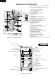
SJ-P43N/43N SJ-P47N/47N DESIGNATION OF VARIOUS PARTS The names in parenthesis are the denominations used in the REPLACEMENT PARTS LIST. 17 1 18 2 3 26 19 4 5 6 7 5 8 20 Plasmacluster 21 22 9 23 24 10 11 12 13 25 19 14 15 16 20 NOTE : 2 star section for storing frozen food only. (not freezing) Figure D-1. External Description 1. Freezer temp. control knob 2. Freezer shelf(Freezer tray) 3. Ice cube maker 4. Ice cube box(Ice storage box) 5. Deodorizing unit 6. Fresh case 7. Refrigerator temp.
SJ-P43N/43N SJ-P47N/47N DIMENSIONS OUTER DIMENSIONS AND CLEARANCE more than 60 more than 680 more than 60 1 more than 60 680 73 16 1320 1022.5 1700 1260 9.5 595 90 660 470 1210 1: Not include the handle (Unit : mm) Fig. E-1(SJ-P43N,SJ-43N) more than 60 more than 680 90 more than 1 60 more than 680 60 1320 1820 1260 9.5 595 470 73 16 1142.5 660 1210 1: Not include the handle (Unit : mm) Fig.
SJ-P43N/43N SJ-P47N/47N INNER DIMENSIONS 502 89 229 The dimensions between shelves can be changed by setting the shelves on the other rails. 232 99 242 99 242 536 536 510 307 307 (172) 126 246 225 502 82 349 226 539 508.5 112 118 518 531 (172.5) 89 (133) 502 321 210 502 188 526 (Unit: mm) 502 89 229 Fig. E-3(SJ-P43N,SJ-43N) 232 99 242 510 126 539 502 225 307 307 (192) 536 99 242 82 526 349 226 536 246 628.5 112 118 518 531 (222.
SJ-P43N/43N SJ-P47N/47N LIST OF ELECTRICAL PARTS ITEMS Thermostat TYPE NAME MM1-8149 Defrost thermostat Thermo. fuse Fan motor Defrost heater Door switch Damper thermostat Defrost timer S101 SF70E 3R00121A MM6-4264 DSD-5 MM1-6173 ND1004M2 Lamp socket Lamp Compressor — — FL1568SD RATING 125V 6A 250V 3A 250V 8A 250V 10A 220-240V 50/60Hz 220-240V 378Ω 250V 0.25A — 220-240V 50/60Hz 250V 1A 240V 15W 220-240V/50Hz SPECIFICATIONS (At normal notch) ON/OFF : -20 / -25˚C Open/Close : 8 / 1˚C Working temp.
SJ-P43N/43N SJ-P47N/47N WIRING DIAGRAM Be sure to replace the electrical parts with specified ones for maintaining the safety and performance of the set. Defrost timer F-Thermostat (BR) (GY) (R) CONNECTED IN TERMINAL BOX TM Lamp CONNECTOR Source Plug MAIN PWB L FM : GRAY : BROWN (live) : ORANGE : YELLOW : RED : PINK : BLUE(neutral) : BLACK : SKY-BLUE : GREEN-YELLOW (earth) : WHITE (W) PC (G-Y) Thermo.
SJ-P43N/43N SJ-P47N/47N E.V. cover ass’y Cabinet ass’y Lead EV-cover ass’y Fan motor FM F-thermostat Def thermo. ass’y Fuse ass’y F-Door GY-1 OR-1 R-1 BR-1 Y-1 BL-1 BK-1 W-1 1 5 2 6 3 7 4 8 1 5 2 6 3 7 4 8 1 2 (W-1) 1 2 Y-2 1 2 3 1 2 3 DOOR HARNESS 1 2 3 Def.
SJ-P43N/43N SJ-P47N/47N E.V. cover ass’y Cabinet ass’y Lead EV-cover ass’y Fan motor FM F-thermostat Def thermo. ass’y Fuse ass’y Def.
LED1 ZD1 PC R21 (1/2W) 680 SW CN4 2 3 1 CN2 CN3 (MAIN PWB) PC : PLASMACLUSTER UNIT (IONIZER-K) (PANEL PWB) F-FM CN1 2 1 2 3 1 1 7 3 5 R17 (1/2W) 1.8 R11 1K R1 R2 VRS1 C15 100 10V R18 10K C13 0.1 Q3 KTA1046 TRNS C10 1 50V C9 0.1 D7 ISS270A Q1 KRA101M C3 0.1 50V C7 0.1 R7 1K (A/D) 13 C2 2200 35V 10 RS2 RS3 4.7K R20 RS1 R8 10K R19 OPEN I IC1 C16 0.1 O I C19 1000 25V 11 IC2 O G C18 0.1 7805 C5 1 50V C20 100 10V PST993E IC3 3 1 2 C6 0.1 C4 0.
SJ-P43N/43N SJ-P47N/47N FUNCTIONS 1. ADJUSTABLE TEMPERATURE CONTROL (1) Temperature control of freezer Thermostat (senses freezer temperature) operates on ON/OFF switchover to control the compressor and cool air circulating fan , and allows the freezer temperature to keep at a suitable temperature. However adjust the freezer temp. control knob as follows depending upon the storing condition of foods. PURPOSE KNOB SETTING MAX(Coldest) For making ice rapidly or fast freezing.
SJ-P43N/43N SJ-P47N/47N 2. DEFROSTING (1) No defrosting operation is necessary No defrosting operation is necessary. As this machine is so designed that a built-in evaporator cools air and a fan circulates cooled air, neither the freezer nor the refrigerator is frosted, though the evaporator is frosted. The frosted evaporator is defrosted automatically due to the function of defrosting timer and heater, requiring no defrosting operation. (2) Where is melted frost brought 1.
SJ-P43N/43N SJ-P47N/47N (4) As a reference to determine the causes of trouble, malfunction and phenomena are described below. Refer to the following when repairing. 1. Disconnection of defrost heater As off-cycle defrosting is performed, the defrosting time is extremely prolonged. Each time defrosting is started, the freezer temperature rises and a portion of ice and stored foods are melted. 2. Melted thermo. fuse or opened-circuit due to the defect of defrost thermostat.
SJ-P43N/43N SJ-P47N/47N 5. PLASMACLUSTER (Only for SJ-P43N,P47N) (1) Plasmacluster is what thing. The ionizer inside the refrigerator will release cluster ions, which are collective mass of positive and negative ions, into the the freezer and refrigertor compartments. The cluster ions inactivate airborne fungus. (2) Plasmacluster Panel 1.When the refrigerator will be operated, the Plasmacluster lamp of the panel will light up. 2.By pushing the button, the lamp goes out or lights up. 3.
SJ-P43N/43N SJ-P47N/47N ASSEMBLING PROCEDURES OF MAIN PARTS AND CAUTIONS CAUTION: DISCONNECT THE UNIT FROM THE POWER SUPPLY BEFORE ANY REPAIRING. 1. R-AIR GUIDER ASSEMBLY A-sealer ag1 Damper thermo. Thermo. cap. sealer R air guider S Plasma holder (Only for SJ-43N,SJ-47N) A-sealer ag3 Ionizer-K A-sealer ag2 Dial sealer Plasma harness (Only for SJ-P43N,SJ-P47N) R air guider Figure A-1 Less than 160 mm (1) Forming sensor of Damper thermo.
SJ-P43N/43N SJ-P47N/47N (3) Fixing of the Ionizer-K.(Only for SJ-P43N,P47N) (3)-1 Connect Ionizer-K and connector of the lead wire. (3)-2 Insert Ionizer-K to Plasma holder. (3)-3 Insert the (3)-2 assembly to R air guider A. R air guider A Plasma harness Ionizer-K 2P Connector should insert surely. Plasma harness Plasma holder Ionizer-K A Paper tape W30×100mm B B Paper tape W30×40mm 2P 2P 2P A SEC. A—A Paper tape W30×40mm SEC.
SJ-P43N/43N SJ-P47N/47N 2. FAN LOUVER AND E.V COVER ASSEMBLY 2-1. How to remove the Fan louver (1) Take out 2 screws. (2) Insert the screwdriver into the air hole of the Fan louver. (3) Press the Fan louver to the left side with the screwdriver,and pull it toward yourself to take off the Fan louver. (4) Fan louver Claw (4) Claw (1) Screw (4) Claw (3) (3) Claw (1) Screw (2) Figure A-4 2-2. E.v cover assembly Motor cushion Fan motor holder B Fan motor holder A E.v cover sealer C Defrost thermo.
SJ-P43N/43N SJ-P47N/47N (2)-2 Insert the terminals of Lead EV-cover ass'y to Fan motor. (2)-3 Fix two Motor cushions to Fan motor, and set it at Fan motor holder A and B. Then fix with Tapping screw. (2)-4 Set Fan clamp to Propeller fan 100 and insert it to the shaft of Fan motor. Fan clamp Fan motor holder B D Fan clamp Motor cushion Fan motor holder A Slit of each Fan clamp and Propeller fan should not be at same position.
SJ-P43N/43N SJ-P47N/47N (4) Inserting of pins After inserting, fix with vinyl tape. F-thermostat 2 (RED, inserted) Defrost thermo. 3 (PINK) Fuse 8 (WHITE) Fan motor 1 , 5 WIRE COLOR FOR FAN MOTOR 100-110V : WHITE 127V : YELLOW 220-240V : BLUE 1 2 3 4 5 6 7 8 F-thermostat 6 (BROWN, inserted) Vinyl tape Fuse 8 (BLACK) Defrost thermo. 7 (BLUE) Note Pins should be inserted surely, and check by pulling it. Figure A-11 Figure A-12 (5) Setting of F-thermostat (5)-3 Set to E.V cover. Stick E.
SJ-P43N/43N SJ-P47N/47N (2) Replacement of Def. heater ass'y. (2)-1 Remove the center screw of Drain support al to take it off from the food liner. 3. DEFROST HEATER (1) Taking-out Evaporator (1)-1. Take out E.v cover ass'y (Fig. A-16). Drain support al Evaporator Screw Food liner convex part Fig. A-19 Fig. A-16 (2)-2 Raise the protrusion part of Drain support al. Then remove Heater cover. (1)-2. As shown in Fig.
SJ-P43N/43N SJ-P47N/47N (2)-4. Replace Def. heater ass'y with new one. (2)-7. Stick the longer wire to the Drain support by aluminum tape (2 pieces), and wind vinyl tape (2 pieces) to lead wires of Def. heater ass'y by aluminum tape as shown in Fig. A-25. Note: Glass cloth tape part shall be both side of Drain support to protect the lead wire from damaged. Heater cover Glass cloth tape Glass cloth tape Def.heater ass’y A A Sec. AA [back side] aluminum tape (W25 X L40) Drain support al Fig.
SJ-P43N/43N SJ-P47N/47N (3) Installing of Evaporator (3)-1. Install Evaporator as shown in Fig. A-16 in the reverse order of Fig. A-17. (3)-2. Correct the deformed fin. NOTE 1. When installing Evaporator, take care not to deform significantly and break the pipes. 2. Take care not to damage the lead wires and hurt yourself by the fin of Evaporator.
SJ-P43N/43N SJ-P47N/47N Dryer Capillary tube Charge pipe Hot pipe Evaporator Charge pipe Compressor Suction pipe S.P. connector Eva-pan pipe Back condenser Figure C-2. Location From Eva-pan pipe ass’y to Back condenser In From Back condenser out to Hot pipe From Compressor to Discharge p connector From Suction pipe to SP connector From Hot pipe to Dryer From Dryer to Capillary tube From SP connector to Compressor From Compressor to Charge pipe Figure C-3.
SJ-P43N/43N SJ-P47N/47N REPLACEMENT PARTS LIST(SJ-P43N/43N-SL1/WH1) REF. NO. PART NO.
SJ-P43N/43N SJ-P47N/47N REF. NO. PART NO. DESCRIPTION Q'TY CODE SJ-P43N SJ-P43N SJ-43N -SL1 -WH1 -SL1 2222222222222- 79 80 81 82 83 87 91 93 94 95 99 100 101 LBND-A019CBE0 PBOX-A132CBFA PBOX-A143CBFA PCOVPA373CBFA PSEL-C080CBEZ LBND-A018CBE0 HGRL-A202CBFA PCAP-A068CBFA PSEL-C137CBEZ PSHEMA231CBEZ PSEL-A562CBE0 PSEL-C138CBEZ PSEL-C139CBEZ Nylon band Terminal box Terminal box-b Terminal cover-b A-sealer ag3 Fastening band a F return cover C sliding cap a E.
SJ-P43N/43N SJ-P47N/47N REF. NO. PART NO.
SJ-P43N/43N SJ-P47N/47N REPLACEMENT PARTS LIST(SJ-P47N/47N-SL1/WH1) REF. NO. PART NO.
SJ-P43N/43N SJ-P47N/47N REF. NO. PART NO. DESCRIPTION Q'TY CODE SJ-P47N SJ-P47N SJ-47N -SL1 -WH1 -SL1 2222222222222- 79 80 81 82 83 87 91 93 94 95 99 100 101 LBND-A019CBE0 PBOX-A132CBFA PBOX-A143CBFA PCOVPA373CBFA PSEL-C080CBEZ LBND-A018CBE0 HGRL-A202CBFA PCAP-A068CBFA PSEL-C137CBEZ PSHEMA231CBEZ PSEL-A562CBE0 PSEL-C138CBEZ PSEL-C139CBEZ Nylon band Terminal box Terminal box-b Terminal cover-b A-sealer ag3 Fastening band a F return cover C sliding cap a E.
SJ-P43N/43N SJ-P47N/47N REF. NO. PART NO.
SJ-P43N/43N SJ-P47N/47N 1 2 3 4 5 6 DOOR PARTS A SJ-P43N,P47N A SJ-43N,47N 3-6 3-6 3-5 3-5 3-5-2 3-10 3-11 B B 3-9 3-8 1-55 3-31 C 2-43 3-5-4 3-30 C 3-5-5 3-7 3-5-3 3-5-3 3-5-1 3-5-1 3-15 D D 3-15-2 3-7 3-19 3-21 5-3 5-5 E E 5-4 3-22 90-15 3-20 5-2 F F 5-2 5-35 3-17 G G 3-15-3 5-1 3-15-1 5-3 SJ-P43N SJ-43N SJ-P47N SJ-47N H 1 2 3 4 33 5 6 H
SJ-P43N/43N SJ-P47N/47N 1 2 3 4 5 6 CABINET PARTS A A 5-9 5-31 B B 5-6 5-17 5-32 2-93 5-18 C C 2-29 2-13 2-93 5-19 D D 5-24 2-91 5-24-1 5-24-2 2-49 1-10 E E 2-49 4-3 2-15 5-25 5-25-1 5-25-2 F F 5-15 2-14 5-13 2-93 2-8 G G 5-16 2-7 2-93 2-7-2 2-7-1 2-8-2 2-7-1 SJ-P43N SJ-43N SJ-P47N SJ-47N H 1 2 3 4 34 5 6 H
SJ-P43N/43N SJ-P47N/47N 1 2 3 4 5 6 CABINET PARTS A A 2-19 1-6 2-63 2-64 2-19 2-23 2-17 1-5 2-16 4-1 2-100 2-65 2-20 1-20 4-1 B B 2-94 2-68 2-21 2-28 2-95 2-22 2-101 1-1 1-9 1-17 2-4 2-70 C 2-44 C 2-69 2-46 4-11 (4-12) 2-2 2-66 1-21 2-72 1-4 2-24 2-79 1-3 2-67 2-99 2-39 (Only for SJ-43N,47N) 2-47 D 2-38 2-78 2-83 6-18 2-73 6-5 1-45 2-71 2-77 2-80 1-50 2-81 1-46 2-82 (Only for SJ-P43N,P47N) 2-46 D (Only for SJ-P43N,P47N) 2-45 2-27 1-22 E E 2-87 2-50 6
SJ-P43N/43N SJ-P47N/47N COPYRIGHT © 2005 BY SHARP CORPORATION ALL RIGHTS RESERVED. No part of this publication may be reproduced, stored in retrieval systems, or transmitted in any form or by any means, electronic, mechanical, photocopying, recording, or otherwise, without prior written permission of the publisher. 43ATUE/ 43ATTE/ 43BTUE/ 43BTTE/ 47ATUE/ 47ATTE/ 47BTUE/ 47BTTE 36 2005 SHARP CORP. (01K0.