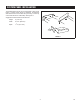
INSTALLATION INSTRUCTIONS Sharp Convection Microwave Drawer & SuperSteam+ Pedestal Model SKCD24U0GS For use with models SMD2499FS and SSC2489DS. IMPORTANT NOTES TO THE INSTALLER • PLEASE READ THESE INSTRUCTIONS THOROUGHLY BEFORE BEGINNING INSTALLATION. • Observe all governing codes, ordinances, and safety instructions. • Refer to these specific models' installation instructions for more information on placement. • Be sure to leave these instructions with the consumer.
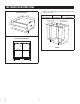
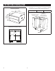
INSTALLATION INSTRUCTIONS 1. Cabinet cutout dimensions. Prepare the cabinet opening as shown in Figure 1. Overall Dimensions 23 1/2" (596.9 MM) Width (B) 24" (610 mm) Height (A) 34 1/2" (876 mm) 23 13/16" (604.8 MM) SUGGESTED ELECTRICAL OUTLET LOCATION 14 7/16" (366.7 MM) MIN 15 3/4" (390.5 MM) MAX *NOTE: INSTALLER PROVIDE TOP FILLER IF NEEDED A Inside Drawer Dimensions C B 21 13/16" (554.0 MM) FIGURE 1 18 11/16" (474.7 MM) 23 11/16" (601.7 MM) E 2 Depth (C) 23 1/2" min.
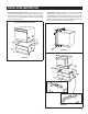
INSTALLATION INSTRUCTIONS SuperSteam+ Oven - Place the oven on a secure surface. Remove the 2 bottom screws (1 on each side of the oven) as showing in Figure 2B. Install the two conversion brackets with the two provided screws (J). See Figure 2C. Carefully place the oven on top of the pedestal in-between the conversion brackets on the left and right. 2. Convection Microwave Drawer - Place the oven on a secure surface. Remove the 4 bottom screws (2 on each side of the oven) as shown in Figure 2A.
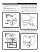
INSTALLATION INSTRUCTIONS 4. Adjust the height of the overall unit to fit your specific opening. The pedestal contains 4 adjustable feet. To adjust, have one person tilt the unit to one side while the other person adjusts the 2 feet on the raised side to the desired height. Repeat this step by tilting the unit to the other side and adjusting the other 2 feet. Ensure that all feet are adjusted equally to balance the unit. See Figure 4. 3.
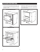
INSTALLATION INSTRUCTIONS 7. Slide the unit into the opening. Plug oven into the wall receptacle prior to pushing the unit all the way in. See Figure 8. The mounting angles of the oven should rest against the installed wooden cleats. 6. Install the wooden cleats. Align the bottom of the cleat to the measurement from Step 5. The pedestal can be installed flush or standard with the face of the cabinet. Depending on the preference, the depth of the cleat position should be adjusted as such. See Figure 6.
INSTALLATION INSTRUCTIONS 8. Open the oven door and pre-drill each hole using a 1/16" (1.6 mm) drill bit. Fasten the unit to the mounting cleats using the 4 mounting screws provided with your oven. See Figure 9A or 9B. 9. Install bottom kickplate. Use the 2 toe kick screws to fasten the plate. The 2 toe kick screws come installed in the unit. Remove these 2 screws prior to positioning the kickplate. See Figure 10.
CUSTOM PANEL INSTALLATION The pedestal drawer fronts can be replaced with custom wood fronts. If custom drawer faces are preferred, the stainless steel drawer faces can be taken off by removing 5 screws (3 on the back side and 2 underneath). See Figure 11. Suggested custom drawer face dimensions: Height 5" (127 mm) Width 23 11/16" (602 mm) Depth 1 3/16" (30.
SHARP ELECTRONICS CORPORATION • 100 Paragon Drive, Montvale, New Jersey 07645 • USA For any other assistance or information about this kit, please call Sharp’s Customer Assistance Center: 1-800-BE-SHARP (1-800-237-4277) SHARP ELECTRONICS OF CANADA LTD • 335 Britannia Road East, Mississauga, Ontario, L4Z 1W9 • Canada For any other assistance or information about this kit, please call 877-278-6709 Mon-Fri: 8am-5pm EST (except statutory holidays)
INSTRUCTIONS D'INSTALLATION Caisson pour tiroir four à micro-ondes et SuperSteam+™ Sharp modèle SKCD24U0GS Peut être utilisé avec les modèles SMD2499FS et SSC2489DS NOTES IMPORTANTES À LA PERSONNE QUI FERA L'INSTALLATION • VEUILLEZ LIRE ATTENTIVEMENT CES INSTRUCTIONS AVANT DE COMMENCER L'INSTALLATION. • Veuillez respecter tous les codes de conduite, toutes les ordonnances et instructions de sécurité.
INSTRUCTIONS D'INSTALLATION 1. Dimensions de la découpe de l'armoire. Préparer l'ouverture de l'armoire comme illustré à la Figure 1. Dimensions générales 596,9 /2" 23 1mm 1/2 po) (596.9 MM) (23 Largeur (B) 610 mm (24 po) Hauteur (A) 876 mm (34 1/2 po) " 23 13/16mm 604,8 (604.8 MM) 13/16 (23 po) EMPLACEMENT DE LA PRISE SUGGESTED ELECTRICAL ÉLECTRIQUE SUGGÉRÉ OUTLET LOCATION 7 14 /mm 16" 366,7 (366.7 MM) MIN (14 7/16 po) MIN 15 3/mm 4" 390,5 (390.
INSTRUCTIONS D'INSTALLATION Four SuperSteam+ - Mettre le four sur une surface solide. Retirer les 2 vis inférieures (1 sur chaque côté du four) comme illustré à la Figure 2B. Installer les deux supports de conversion à l'aide des deux vis fournies (J). Voir la Figure 2C. Déposer soigneusement le four sur le dessus du caisson entre les supports de conversion situés à gauche et à droite. 2. Tiroir four à micro-ondes et à convection - Mettre le four sur une surface solide.
INSTRUCTIONS D'INSTALLATION 4. Ajuster la hauteur totale de l'unité pour correspondre à l'ouverture. Le caisson est équipé de 4 pattes ajustables. Pour ajuster, demander à quelqu'un d'incliner l'unité de côté pendant qu'une autre personne ajuste les deux pattes sous le côté soulevé à la hauteur nécessaire. Répéter cette étape en inclinant l'unité de l'autre côté et en ajustant les deux autres pattes. Veiller à ce que toutes les pattes soient ajustées de façon égale afin que l'unité soit équilibrée.
INSTRUCTIONS D'INSTALLATION 7. Glisser l'unité dans l'ouverture. Brancher dans la prise murale avant de pousser l'unité complètement à l'intérieur. Voir la Figure 8. Les angles de montage du four doivent reposer contre les taquets en bois installés. 6. Installer les taquets en bois. Aligner le dessous des taquets avec les mesures prises à l'étape 5. Le caisson peut être encastré ou installé de façon standard avec la façade de l'armoire.
INSTRUCTIONS D'INSTALLATION 8. Ouvrir la porte du four et pré-percer chaque trou avec une mèche de 1,6 mm (1/16 po). Fixer l'unité aux taquets en utilisant les 4 vis pour les taquets de fixation fournies avec votre four. Voir la Figure 9A ou 9B. 9. Installer le coup-de-pied. Utiliser les deux vis à coup-depied pour fixer la plaque. Les deux vis à coup-de-pied sont déjà installée dans l'unité. Retirer ces deux vis avant de placer le coup-de-pied. Voir la Figure 10.
INSTALLATION DE FAÇADES PERSONNALISÉES Les façades des tiroirs du caisson peuvent être remplacées avec des façades en bois personnalisées. Si vous préférez installer des façades personnalisées, les façades en acier inoxydable peuvent être enlevées en retirant les 5 vis (3 à l'arrière et deux en dessous). Voir la Figure 11.
SHARP ÉLECTRONIQUE DU CANADA LTÉE • 335, rue Britannia Est, Mississauga, Ontario, L4Z 1W9 Pour tout autre type d'aide ou de renseignements concernant cette trousse, veuillez communiquer 877-278-6709 De lundi au vendredi : de 8 h à 17 h est (sauf les jours fériés) TINSEB584MRR0 Mar 19, 2021