
Use Care & Installation Guide

E 1
C
N
H
E
F
D
A
B
J
L
I
M
K
G
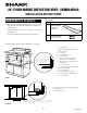
Note: the face of the shelf must
sit 1
3
/4" (44.45 mm) back from
the face of the cabinet.
cabinet face
shelf face
O
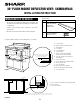
24" Flush Mount DeFlector Vent: sKMD24F0As
INSTALLATION INSTRUCTIONS
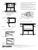
1. Prepare cabinet opening as shown in Figures 1, 2A, 2B, 2C.
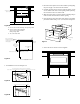
C
L
Top view
A
Anti-Tip block
Mounting cleat
B
C
Drawer face
Cabinet
face
Note: the mounting surface of the finished cleat must sit 1
1
/16" (26.97 mm) back
from the face of the cabinet [pushing the face of the drawer out
1
/4" (6.35 mm)].
Figure 1
Figure 2A
Important notes to the Installer
• Read all of the Installation Manual that is included with
the Microwave Drawer before installing in the ush mount
conguration.
• Observe all governing codes, ordinances, and safety
instructions.
•Be sure to leave these instructions with the consumer.
Parts includes:
Qty. Part number
1
PREF-B019MRP0
Flush Mount
Deector Vent
2
LX-CZB055MRE0
Mounting screws
TINSEB541MRR2
A. 6" (152.40 mm)
B. Suggested electrical outlet location
C. Anti-Tip block
D. 5" (127 mm)
E. 3-1/2" (88.90 mm)
F. 4" (101.60 mm)
G. 24-3/16" (614.35 mm) minimum
24-1/2" (622.3 mm) maximum
H. 14-13/16" (376.24 mm) to bottom of
Anti-Tip block
I. 1-1/16" (26.97 mm)
J. 23-1/2" (596.90 mm) minimum depth
K. 22-1/8" (561.97 mm)
L. 1-3/4" (44.45 mm)
M. 16-7/8" (428.62 mm) opening
N. Floor must support 100 lb (45.4 kg)
O. 1-3/4" (44.45 mm)
A. 22" (558.8 mm) mounting cleat opening width
B. 1/4" (6.35 mm)
C. 1-1/16" (26.97 mm)