
Installation Manual


2E
F
E
H
D
G
I
A
B
C
J
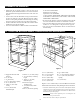
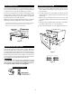
CLEARANCES AND DIMENSIONS
• Dimensions that are shown in Figure 1 must be used. Given
dimensions provide minimum clearance. Locate electrical outlet
in the shaded area in the upper left-hand corner of the cutout. See
Figure 9.
• Contact surface must be solid and level. Pay special attention to
the oor on which the Convection Microwave Drawer will sit.
The oor of the opening should be constructed of plywood strong
enough to support the weight of the oven (about 100 pounds).
• Check location where the Convection Microwave Drawer will be
installed for proper electrical supply.
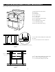
• Your oven can be built into a cabinet or wall as a stand-alone unit.
It can also be installed under:
Wall Ovens: Gas or Electric
SuperSteam oven: SSC2489DS
Cooktop Models: SDH3042DB, SDH3652DB, SCR3042FB,
SCR2442FB, SCR3041GB, SCH3043FB, SCH2443FB,
SDH3042DB or SDH3652DB.
• Be sure that the clearance of the oor between the wall oven and
the Convection Microwave Drawer is a minimum of 2-inches.
• The Convection Microwave Drawer interior will easily accom-
modate a 9" x 13" oblong dish or a bag of microwave popcorn.
• The oven can also be mounted ush. Please see instructions for
ush mounting.
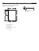
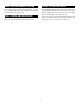
24" CONVECTION MICROWAVE DRAWER STANDARD MOUNT AND MEASUREMENTS
B
C
G
D
A
B
C
D
E
I
F
G
H
I
J
K
L
M
A
F
E
Figure 1
Figure 2
A. Suggested electrical outlet
location*
B. 5" (127 mm)
C. 4" (101.60 mm)
D. 22
3
/8" (568.32 mm) opening
E. 19
3
/8" (492.12 mm)
F. Allow
5
/8" (15.87 mm)
overlap
G. 23
1
/2" (596.90 mm)
minimum depth
H. Allow
1
/8" (3.17 mm) overlap
I. 36" (914.40 mm) countertop
height
J. Allow
1
/2" (12.7 mm)
minimum space
K. Floor must support
100 lb (45.4 kg)
L. 24" (609.60 mm) cabinet
minimum
M. 19
3
/8" (492.12 mm) opening
Figures 1 and 2 contain many Convection Microwave Drawer
measurements for reference when planning the drawer’s location.
* Can also be installed using an electrical outlet in an adjacent cabinet
within the area where the provided electrical cord can reach. Power
cord access hole in cabinet should be a minimum 1
1
/2" diameter hole
and deburred of all sharp edges.
IMPORTANT
Always allow sufcient power cord length to the
electrical outlet to prevent tension.
Always check electrical codes for requirements.
A. 2
1
7
/8" (555.56 mm)
B. 4
11
/16" (119.06 mm)
C. 1
3
/4" (44.45 mm)
D. 20
7
/8" (530.23 mm)
E. 23
5
/8" (600.07 mm)
F. 19
1
/2" (495.3 mm)
G. 19
1
/4" (488.95 mm)
H. 1
5
/8" (41.27 mm) door thickness
I. 15
1
/2" (393.7 mm) auto drawer
opening
J. 4" (101.60 mm)