
SMO1652DS Installation Guide


8
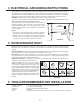
8 OVEN INSTALLATION
THIS OVEN CANNOT BE PROPERLY INSTALLED WITHOUT REFERRING TO THE MOUNTING
INSTRUCTIONS FOUND ON BOTH TEMPLATES.
READ AND FOLLOW MOUNTING INFORMATION ON BOTH TOP CABINET AND WALL TEMPLATES.
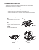
MOUNTING PLATE
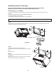
Step 1. Setup position
a. Draw a line down the middle of the studs(See the Wall
Construction, page 1)
b. Draw a vertical line on the wall at the center of the 30” wide
space. See Figure 18.
NOTE: Use the wall template for the rear wall.
Reference Wall Template prior to proceeding.
Installation of this product require 2 persons.
Step 2. Drilling
Reference the Wall Template.
A
C
C
B
C
C
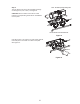
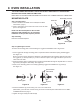
Step 3. Tightening the screws
To attach the mounting plate to the wall using the toggle bolt assemblies and/or lag screws:
1. Insert toggle bolts through mounting plate at required locations and add the spring loaded toggles.
See Figure 19.
Be sure you leave space at least the thickness of the wall between the mounting plate and the end of
the toggle nut, (in closed position). If you do not leave this space, the toggle nut will not open on the
other side of the wall.
2. Position mounting plate on wall and insert toggle bolt assemblies through the drywall holes or start the
lag-screw(s) through the wall stud(s). See Figure 20.
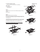
3. Next, secure mounting plate to the wall by tightening toggle bolt assemblies or lag screw(s).
See Figure 21.
4. Drill 3/16” diameter lag screw hole(s), into one or more wall studs.
(Remember, you must have at least one lag screw into a wall stud.)For stud location refer to WALL
CONSTRUCTION see page 3
5. Tighten the lag screw(S) into wall stud(S)
Mounting plate
Power Supply Cord Hole
House Duct
Mounting Plate
Dry Wall
Space more than
wall thickness
Figure 18
Figure 19 Figure 20 Figure 21