Network Camera SNB-5000/SND-5080/SND-5080F/SNV-5080 User Manual Before installing and operating this product, please read this manual thoroughly.
overview IMPORTANT SAFETY INSTRUCTIONS 1. Read these instructions. 2. Keep these instructions. 3. Heed all warnings. 4. Follow all instructions. 5. Do not use this apparatus near water. 6. Clean only with dry cloth. 7. Do not block any ventilation openings, Install in accordance with the manufacturer’s instructions. 8. Do not install near any heat sources such as radiators, heat reaisters, stoves, or other apparatus (including amplifiers) that produce heat. 9.
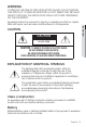
WARNING TO REDUCE THE RISK OF FIRE OR ELECTRIC SHOCK, DO NOT EXPOSE THIS PROCUCT TO RAIN OR MOISTURE. DO NOT INSERT ANY METALLIC OBJECT THROUGH THE VENTILATION GRILLS OR OTHER OPENNINGS ON THE EQUIPMENT. Apparatus shall not be exposed to dripping or splashing and that no objects filled with liquids, such as vases, shall be placed on the apparatus M OVERVIEW CAUTION CAUTION RISK OF ELECTRIC SHOCK. DO NOT OPEN CAUTION : TO REDUCE THE RISK OF ELECTRIC SHOCK. DO NOT REMOVE COVER (OR BACK).
overview Disconnection Device Disconnect the main plug from the apparatus, if it’s defected. And please call a repair man in your location. When used outside of the U.S., it may be used HAR code with fittings of an approved agency is employed. CAUTION These servicing instructions are for use by qualified service personnel only. To reduce the risk of electric shock do not perform any servicing other than that contained in the operating instructions unless you are qualified to do so.
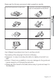
Please read the following recommend safety precautions carefully. Do not install on a surface where it is exposed to direct sunlight, near heating equipment or heavy cold area. Do not place this apparatus near. Do not attempt to service this apparatus yourself. Do not place a glass of water on the product. Do not install near any magnetic sources. Do not block any ventilation openings. Do not place heavy items on the product.
overview This equipment has been tested and found to comply with the limits for a Class A digital device, pursuant to part 15 of the FCC Rules. These limits are designed to provide reasonable protection against harmful interference when the equipment is operated in a commercial environment. This equipment generates, uses, and can radiate radio frequency energy and, if not installed and used in accordance with the instruction manual, may cause harmful interference to radio communications.
CONTENTS OVERVIEW INSTALLATION & CONNECTION 24 Important Safety Instructions Product Features Recomended PC Specifications What’s Included At a Glance (SNB-5000) At a Glance (SND-5080) At a Glance (SND-5080F) At a Glance (SNV-5080) 24 26 28 32 33 Installation (SND-5080) Installation (SND-5080F) Installation (SNV-5080) Mounting the Lens Inserting/Removing an SD Memory Card Memory Card Information (Not Included) Connecting with other Device 36 37 NETWORK CONNECTION AND SETUP 42 42 43 44 45 46 47 50
overview CAMERA SETUP 53 WEB VIEWER 62 SETUP SCREEN 70 APPENDIX 87 8_ overview 53 53 How to use the Menu Key Camera Menu Setup 62 63 64 66 67 68 Connecting to the Camera Login Installing Silverlight Runtime Using the Live Screen Using OSD Screen Menu Playback 70 70 73 77 83 Setup Audio & Video Setup Network Setup Event Setup System Setup 87 89 91 93 Camera Specification Network Specification Troubleshooting GPL/LGPL Software License
PRODUCT FEATURES RECOMENDED PC SPECIFICATIONS y CPU : Pentium4 / 2.4GHz or higher y Operating System : Windows XP, VISTA, 7 Mac OS y Resolution : 1280X1024 pixels or higher y RAM : 1GB or higher y Web Browser : Internet Explorer 7.0 or higher Firefox, Google Chrome, Safari y Video Memory : 128MB or higher English _9 M OVERVIEW y HD Video Quality Supports up to 1.3 mega pixels of HD video quality. y H.264/MPEG-4/MJPEG Multi-Streaming This network camera supports the H.
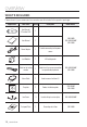
overview WHAT’S INCLUDED Please check if your camera and accessories are all included in the product package.
Appearance Quantity Description C Mount Adapter Auto Iris Lens Connector 1 Used to install the camera lens Camera Holder (Mount) 1 Used to install the camera holder Camera Holder (Mount) Screws 2 Used to install the mount ASSY-Screw Tapping 4 Used for installation on the wall or ceiling L Wrench 1 Used to remove/fix the dome cover Plastic Anchor 4 For fixing a screw, Inserted in a hole (reinforced anchoring force) Model Name SNB-5000 M OVERVIEW Item Name SNV-5080 Tapping Screw SND-5
overview AT A GLANCE (SNB-5000) Front Side SNB-50 www.sam 00 sungcc tv.c om Item M Description Camera Holder (Mount) Holes Used when you mount the camera onto the bracket by fixing the camera holder (mount) adaptor with the bracket. Auto Iris Lens (Optional) Installed on the lens adaptor. Auto Iris Lens Connector Used to supply power and output signal to control the iris of the lens. Wipe out a dirty surface of the lens softly with a lens tissue or cloth to which you have applied ethanol.
Rear Side AUDIO OUT AUDIO IN SD CARD SD SYSTEM POWER 1 2 3 4 5 1 : ALARM IN 4 : 2 : ALARM OUT 5 : GND 3 : ALARM COM Item SD Memory Card Compartment M OVERVIEW VIDEO RESET NETWORK ACT LINK GND AC 24V DC 12V Description Compartment for the SD memory card. AUDIO OUT Terminal for audio output. AUDIO IN Terminal for audio input. Audio terminal ON : A memory card is inserted and operates normally. SD Flashing : Failed to record, insufficient space, or inserted abnormally.
overview Resets the camera settings to the default. Press and hold it for about 5 seconds to turn off the system indicator and restart the system. Reset Button J Resetting the camera requires reconfiguration of network settings (IP address, subnet mask, gateway address etc.) using the IP Installer software application. Power Port Used to plug the power cable. GND Used for earth-grounding. Network Port Used to connect a PoE or LAN cable. ALARM IN Used to connect the alarm input signal.
AT A GLANCE (SND-5080) Appearance M OVERVIEW Item Description Dome Cover Dome cover for the lens and unit protection. Main unit Main unit includes the lens, switch board, PCB boards and screws. Power Port Used to plug the power cable. Video Out Port Video signal output port connected to the monitor. Network Port Used to connect a PoE or LAN cable. Audio In Jack Used to connect to a microphone. Audio Out Jack Used to connect to speakers.
overview Inside 3 Item Alarm In / Out terminals SD Memory Card Compartment Description ALARM IN Used to connect the alarm input signal. ALARM OUT Used to connect the alarm output signal. ALARM COM Common port where the alarm output signal is connected. GND Used for earth-grounding. Compartment for the SD memory card. Resets the camera settings to the default. Press and hold it for about 5 seconds to turn off the system indicator and restart the system.
Components 1 2 7 8 Item Description Inner Cover Cover for the main unit’s protection. Side wing hooks By lifting it while gently pressing the both ends, you can separate the inner cover. ZOOM lever Turn the barrel left or right to adjust the zoom, and turn the knob clockwise to lock the zoom. Focus lever Turn the barrel left or right to adjust the focus, and turn the knob clockwise to lock the focus. SD Memory Card Compartment Compartment for the SD memory card.
overview AT A GLANCE (SND-5080F) Appearance Item 7 Description Dome Cover Dome cover for the lens and unit protection. Main unit Main unit includes the lens, switch board, PCB boards and screws. Power Port Used to plug the power cable. Video Out Port Video signal output port connected to the monitor. Network Port Used to connect a PoE or LAN cable. Audio In Jack Used to connect to a microphone. Audio Out Jack Used to connect to speakers.
Inside M OVERVIEW 3 Item Description ALARM IN Alarm In / Out terminals ALARM OUT Used to connect the alarm output signal. ALARM COM Common port where the alarm output signal is connected. GND SD Memory Card Compartment Used to connect the alarm input signal. Used for earth-grounding. Compartment for the SD memory card. Resets the camera settings to the default. Press and hold it for about 5 seconds to turn off the system indicator and restart the system.
overview Components 3 4 5 Item Description Inner Cover Cover for the main unit’s protection. Side wing hooks By lifting it while gently pressing the both ends, you can separate the inner cover. ZOOM lever Turn the barrel left or right to adjust the zoom, and turn the knob clockwise to lock the zoom. Focus lever Turn the barrel left or right to adjust the focus, and turn the knob clockwise to lock the focus.
AT A GLANCE (SNV-5080) Appearance M OVERVIEW Item Description Dome Cover Dome cover for the lens and unit protection. Main unit Main unit includes the lens, switch board, PCB boards and screws. Power Port Used to plug the power cable. Video Out Port Video signal output port connected to the monitor. Network Port Used to connect a PoE or LAN cable. Audio In Jack Used to connect to a microphone. Audio Out Jack Used to connect to speakers.
overview Inside 3 Item Description ALARM IN Alarm In / Out terminals ALARM OUT Used to connect the alarm output signal. ALARM COM Common port where the alarm output signal is connected. GND SD Memory Card Compartment Used to connect the alarm input signal. Used for earth-grounding. Compartment for the SD memory card. Resets the camera settings to the default. Press and hold it for about 5 seconds to turn off the system indicator and restart the system.
Components 3 4 Item Description Inner Cover Cover for the main unit’s protection. Side wing hooks By lifting it while gently pressing the both ends, you can separate the inner cover. ZOOM lever Turn the barrel left or right to adjust the zoom, and turn the knob clockwise to lock the zoom. Focus lever Turn the barrel left or right to adjust the focus, and turn the knob clockwise to lock the focus. Monitor Out Using the test monitor cable, you can connect to a mobile display for camera test.
installation & connection INSTALLATION (SND-5080) Precautions before installation Ensure you read out the following instructions before installing the camera: y Select an installation site (ceiling or wall) that can endure at least 5 times of the camera weight. y Stuck-in or peeled-off cables can cause damage to the product or a fire. y For safety purposes, keep anyone else away from the installation site. And put aside personal belongings from the site, just in case. Installing the camera 1.
2. To fix the camera position, hold down either hook of the inner cover and lift it up. M INSTALLATION & CONNECTION 3. Push the release lock out while turning the main unit in the direction to remove the bracket. If this doesn't work, use the hole on the bottom of the bracket to turn the bracket in the direction. 4. Use the provided screws (x3) to fix the bracket to a desired position (ceiling or wall).
installation & connection INSTALLATION (SND-5080F) Removing the dome cover 1. Hold down the bottom lock lever while removing the cover with the other hand. Removing the cover reveals the main unit and inner cover. 2. To fix the camera position, hold down both hooks of the inner cover while lifting it up. Ceiling Mount 1.
3. Insert the camera assembly into the hole so that it fits to the camera hole, and fix the assembly using the assembly screw tappings (TH, M4xL30). (x3) 4. Close the dome cover. M INSTALLATION & CONNECTION 5. Fix the cover to the main unit. Fit the protruding part inside the cover into the corresponding hole of the main unit, and turn the cover to fix it. To add an alarm cable 1. For this, first you should remove the dome cover from the housing. 2. Pull out the protruding rubber bar as shown. 3.
installation & connection INSTALLATION (SNV-5080) Disassembling To connect the alarm in/out, the dome cover and lens cover are to be separated. 1. Using the L-wrench provided, loosen 3 screws by turning them counterclockwise and separate the dome cover. 2. Lift up the inner cover while gently pressing its both ends to separate it from the unit.
Optional Accessories for Installation For your easier installation, you can purchase appropriate optional accessories available. 1. WALL MOUNT ADAPTOR(SCX-300WM)/ HANGING MOUNT(SCX-300HM) This adaptor is used when installing the dome camera onto a wall. M INSTALLATION & CONNECTION 2. CEILING MOUNT ADAPTOR(SCX-300CM)/ HANGING MOUNT(SCX-300HM) This adaptor is used when installing the dome camera on a concrete ceiling. 3.
installation & connection 4. CORNER MOUNT ADAPTOR (SCX-300KM) This is an adaptor for WALL MOUNT ADAPTOR (SCX-300WM) installation on the corner of wall joint. Installing on the ceiling directly 1. Using the L-wrench provided, loosen 3 screws by turning them counterclockwise and separate the dome cover. 2. Loosen 3 screws by turning them counterclockwise, press both left and right lock releases inwards (in arrow direction) to unlock the stopper, and then separate the camera from the case.
3. Drill holes (diameter 5mm, more than 35mm deep) on the ceiling by matching to the holes on the case bed, and insert plastic anchors (HUD 5) fully into the holes. Fix the case bed on the ceiling by using Tapping Screws (TH M4xL30). (4 places) 5. Adjust the lens aiming to your desired direction. 6. Assemble the Dome Cover. For waterproof purpose, fix and secure the bolt using L-wrench provided.
installation & connection MOUNTING THE LENS Disconnect the power before proceeding. M The C lens and CS lens are not included in the product package. You must use the mega lens only for this purpose. Mounting the CS lens Turn the optional CS lens clockwise to insert it. SNB-50 www.sam 00 sungcc tv.c om CS Lens Mounting the C lens Turn the C mount adaptor clockwise to insert it and do the same with the C lens. SNB-50 www.sam 00 sungcc tv.
Connecting the Auto Iris Lens connector Insert the lens connector into the corresponding hole of the camera. www.sam 00 sungcc tv.c om Focusing Turn the lens left or right to control the zoom and focus the lens so that you can view a clear, sharp object. INSERTING/REMOVING AN SD MEMORY CARD Inserting an SD Memory Card Push the SD memory card in the direction of the arrow shown in the diagram. 000 .com SNB-5msungcctv www.
installation & connection J Do not insert the SD memory card while it’s upside down by force. Otherwise, it may damage the SD memory card. Removing an SD Memory Card Gently press down on the exposed end of the memory card as shown in the diagram to eject the memory card from the slot. 000 .com SNB-5msungcctv www.
M INSTALLATION & CONNECTION J Pressing too hard on the SD memory card can cause the card to shoot out uncontrollably from the slot when released. To remove the SD memory card, set to OFF from and press [Apply]. (page 78) If you saved data in the SD memory card, removing the SD memory card will cause damage to the data stored in the card. If the SD memory is inserted, the SD LED indicator on the rear of the camera will turn on.
installation & connection MEMORY CARD INFORMATION (NOT INCLUDED) What is a memory card? The memory card is an external data storage device that has been developed to offer an entirely new way to record and share video, audio, and text data using digital devices. Selecting a memory card that’s suitable for you Your camera supports SDHC memory cards. You may, however, experience compatibility issues depending on the model and make of the memory card.
CONNECTING WITH OTHER DEVICE SD M INSTALLATION & CONNECTION AUDIO OUT AUDIO IN Monitor SD CARD SYSTEM POWER VIDEO RESET 1 2 3 4 5 1 : ALARM IN 4 : 2 : ALARM OUT 5 : GND 3 : ALARM COM NETWORK ACT LINK GND AC 24V DC 12V Power Network Monitor Out Power Monitor Network English _37
installation & connection Connecting to the monitor Connect the [VIDEO] port of the camera to the video input port of the monitor. M In the initial installation of the camera, you can connect the camera to the monitor for checking the connection status. You must set
Connecting to Audio Input/Output Microphone Network 00 tv.com SNB-am50sungcc www.
installation & connection 1. Connect the AUDIO IN port of the camera with the microphone directly or LINE OUT port of the amplifier that the microphone is connected to. 2. Connect the AUDIO OUT port of the camera with the LINE IN port of the speaker. 3. Check the specifications for audio input. y Audio Codec G.711 PCM. μ-law 64kbps 8kHz sampling y Full duplex Audio y Audio in Used for mono signal line input (Max.2.4 Vpp) y Audio out Used for mono signal line output (Max.2.
Connecting to the I/O port box Connect the Alarm I/O signal to the corresponding port of the rear port box. AUDIO OUT AUDIO IN 1 2 3 4 5 SD CARD SD SYSTEM POWER RESET 1 2 3 4 5 1 : ALARM IN 4 : 2 : ALARM OUT 5 : GND 3 : ALARM COM 1 : ALARM IN 4 : 2 : ALARM OUT 5 : GND 3 : ALARM COM NETWORK ACT LINK GND AC 24V DC 12V 5 4 3 2 1 1 : ALARM IN 4 : 2 : ALARM OUT 5 : GND 3 : ALARM COM y y y y ALARM IN : Used to connect the alarm input signal.
network connection and setup You can set up the network settings according to your network configurations. CONNECTING THE CAMERA DIRECTLY TO LOCAL AREA NETWORKING Connecting to the camera from a local PC in the LAN 1. Launch an Internet browser on the local PC. 2. Enter the IP address of the camera in the address bar of the browser. SNB-50 www.samsu00 ngcctv.com Camera INTERNET SNB-50 www.samsu00 ngcctv.
CONNECTING THE CAMERA DIRECTLY TO A DHCP BASED DSL/CABLE MODEM INTERNET SNB-50 www.samsu00 ngcctv.com DSL/Cable Modem External Remote PC Camera 1. Use the cross LAN cable to connect the network cable directly to your PC. 2. Run the IP Installer and change the IP address of the camera so that you can use the web browser on your desktop to connect to the Internet. 3. Use the Internet browser to connect to the camera. 4. Move to [Setup] page. 5. Move to [Network] – [DDNS] and configure the DDNS settings.
network connection and setup CONNECTING THE CAMERA DIRECTLY TO A PPPOE MODEM INTERNET SNB-50 www.samsu00 ngcctv.com PPPoE Modem External Remote PC Camera DDNS Server (Data Center, KOREA) 1. Use the cross LAN cable to connect the network cable directly to your PC. 2. Run the IP Installer and change the IP address of the camera so that you can use the web browser on your desktop to connect to the Internet. 3. Use the Internet browser to connect to the camera. 4. Move to [Setup] page. 5.
CONNECTING THE CAMERA TO AN IP ROUTER WITH THE PPPOE/CABLE MODEM This is for a small network environment such as homes, SOHO and ordinary shops. SNB-50 www.samsu00 ngcctv.com INTERNET www.samsu00 ngcctv.
network connection and setup IP ADDRESS SETUP Buttons used in IP Installer Item Description Device Name Model name of the connected camera. Click the column to sort the list by model name. However, search will be stopped if clicked during the search. Mode Displays either or for the current network connection status. MAC(Ethernet) Address Ethernet address for the connected camera. Click the column to sort the list by Ethernet address.
This function is not currently implemented. URL DDNS URL address enabling access from the external Internet. However, this will be replaced with the of the camera if DDNS registration has failed. IPv4 Scans for cameras with the IPv4 setting. IPv6 Scans for cameras with the IPv6 setting. Search Scans for cameras that are currently connected to the network. However, this button will be grayed out if neither IPv4 nor IPv6 is checked.
network connection and setup 3. In the
pane, provide the necessary information. MAC (Ethernet) Address : The MAC (Ethernet) address of the applicable camera will be set automatically so you don't need to input it manually. If using an IP router y IP Address : Enter an address falling in the IP range provided by the IP router. ex) 192.168.1.2~254, 192.168.0.2~254, 192.168.XXX.2~254 y Subnet Mask : The of the IP router will be the of the camera.If the IP router has more than one camera connected Configure the IP related settings and the Port related settings distinctly with each other. Category Camera #1 Camera #2 IP Address Subnet Mask Gateway 192.168.1.200 255.255.255.0 192.168.1.1 192.168.1.201 255.255.255.0 192.168.1.1 Port related settings HTTP Port VNP Port 80 4520 10000 4530 M If the is set other than 80, you must provide the number in the address bar of the Internet browser before you can access the camera.
network connection and setup DYNAMIC IP SETUP Dynamic IP Environment Setup y Example of the dynamic IP environment - If an IP router, with cameras connected, is assigned an IP address by the DHCP server - If connecting the camera directly to modem using the DHCP protocols - If IPs are assigned by the internal DHCP server via the LAN Checking the dynamic IP 1. From a local PC, run to display a list of cameras that are assigned . 2.
PORT RANGE FORWARD (PORT MAPPING) SETUP If you have installed an IP router with a camera connected, you must set the port range forwarding on the IP router so that a remote PC can access the camera in it. Manual Port Range Forwarding M NETWORK CONNECTION AND SETUP 1. From the Setup menu of the IP router, select . For setting the port range forward for a third-party IP router, refer to the user guide of that IP router. 2.
network connection and setup CONNECTING TO THE CAMERA FROM A SHARED LOCAL PC 1. Launch . It will scan for connected cameras and display a list of them. 2. Double-click a camera to access. The Internet browser starts and connects to the camera. M You can also access the camera in such way you type the IP address of the found camera in the address bar of the Internet browser.
camera setup HOW TO USE THE MENU KEY Follow the steps below if you run the Web Viewer for setting the menus. 1. Launch the Web Viewer. M CAMERA SETUP 2. Click [Camera Menu ( )] in the left corner of the Live screen. The camera setup menu appears. 3. Use the Up/Down (▲/▼) buttons to move to a desired item. 4. To change the value of a selected item, use the Left/Right (◄/►) buttons. To break down to a sub-menu structure, )] on the selected item.
camera setup 2. Configure the and settings as necessary. y SSDR : Adjust the level of the dynamic range. y D-RANGE : Select the amplitude area of the dynamic range. SSDR SETUP SSDR D-RANGE RETURN 8 NARROW 3. When completed, select to return to the previous screen. White Balance Setup You can correct the image colors based on white under any lighting conditions. ▲/▼ Ö ◄/► Ö ENTER Ö ▲/▼ Ö ◄/► Ö ENTER 1. Move to and select a setting value.
Custom Backlight Setup You can specify a desired area on the video manually and set the area to be displayed more clearly. ▲/▼ Ö ◄/► Ö ENTER Ö ▲/▼/◄/► Ö ENTER 1. Move to . MAIN SETUP SSDR WHITE BAL BACKLIGHT EXPOSURE SPECIAL EXIT 3. Set the BLC . You can change the level to adjust the brightness of the monitoring area. 4. Set the levels to specify the target area. 5. When completed, select to return to the previous screen.
camera setup HLC (Highlight Compensation) Setup When a strong light such as streetlamp or headlight faces forward to the camera, you can mask that exposed area in order to protect it from being saturated. ▲/▼ Ö ◄/► Ö ENTER Ö ▲/▼ Ö ◄/► Ö ENTER 1. Select . 2. Select . MAIN SETUP SSDR WHITE BAL BACKLIGHT EXPOSURE SPECIAL EXIT 3. Set the and the . y LEVEL : Adjust the brightness level so as to remove the incoming highlight from a specific condition.
Exposure Setup You can adjust the exposure level of the camera. ▲/▼ Ö ENTER Ö ▲/▼/◄/► Ö ENTER Ö ▲/▼/◄/► Ö ENTER 1. Move to and select a setting value. MAIN SETUP ON ATW OFF 2. Select each item and set it appropriately. y BRIGHTNESS : Adjust the screen EXPOSURE SETUP brightness. BRIGHTNESS 50 y IRIS : If set to , you can IRIS AUTO SHUTTER --adjust the iris of the camera manually.
camera setup y SENS-UP : Automatically senses the darkness level at night or in a low contrast scene and extends the accumulation time accordingly for a bright and sharp image. SENS-UP LIMIT SETUP LIMIT RETURN 2X If you set the shutter mode to MANUAL/ FLICKERLESS, SENS-UP mode will be deactivated. The greater the video accumulation factor is, the brighter the screen is but the afterimage of a moving object grows accordingly. - AUTO : Set the work condition to Auto mode in a low contrast scene. 3.
3. Use alphanumeric characters in the list and enter a desired title in the bottom input line. You can enter up to 15 characters for the title. _______________ M CAMERA SETUP 4. Select and specify where to display the camera title. When the camera title is displayed, use the direction buttons to specify the position; Click OK to return to the previous menu. CAMERA TITLE SETUP A BCD E F G H I J K L M NO P Q R S T U V W X Y Z abcde f g h i j k l m _n o p q r s t u v w x y z .
camera setup Day/Night Mode Setup You can switch the mode to adjust the black and white level as well as the colors. ▲/▼ Ö ◄/► Ö ENTER Ö ▲/▼ Ö ◄/► Ö ENTER 1. Select . MAIN SETUP SSDR WHITE BAL BACKLIGHT EXPOSURE SPECIAL EXIT 2. Select , and specify a desired mode setting value. y AUTO : Displays in color mode during normal daytime and switches to black and white mode in a low contrast scene at night. Press the [Enter ( )] button to adjust the switching interval between the two modes.
Image Adjustment You can configure the sharpness, gamma level, and color settings of an image to your preference. ▲/▼ Ö ◄/► Ö ENTER Ö ▲/▼ Ö ◄/► Ö ENTER 1. Select . MAIN SETUP ON ATW OFF 2. Select . SPECIAL SETUP CAM TITLE OSD COLOR DAY/NIGHT IMAGE ADJ RETURN 3. Select each item and set it appropriately. If selecting , you can IMAGE SETUP adjust the sharpness of the image. SHARPNESS y SHARPNESS : Adjust the overall sharpGAMMA COLOR LEVEL ness of the image.
web viewer CONNECTING TO THE CAMERA Normally, you would 1. Launch the Internet browser. 2. Type the IP address of the camera in the address bar. ex) • IP address (IPv4) : 192.168.1.100 http://192.168.1.100 - the Login dialog should appear. • IP address (IPv6) : 2001:230:abcd: ffff:0000:0000:ffff:1111 http://[2001:230:abcd:ffff:0000 :0000:ffff:1111] If the HTTP port is other than 80 1. Launch the Internet browser. 2. Type the IP address and HTTP port number of the camera in the address bar.
To check the DDNS address If the camera is connected directly to the DHCP cable modem, DSL modem, or PPPoE modem, the IP address of your network will be changed each time you try to connect to the ISP (Internet Service Provider) server. If this is the case, you will not be informed of the IP address changed by DDNS. LOGIN The default user ID is "admin", and the default password is "4321". 1. Enter "admin" in the input box. 2. Enter "4321" in the input box.
web viewer This network camera uses Microsoft Silverlight for displaying the video. INSTALLING SILVERLIGHT RUNTIME If your PC has not installed Silverlight Runtime or has just installed an old runtime version, you will be redirected to the Silverlight Runtime installation page automatically when accessing the web viewer. 1. Click . 2. When the file download dialog pops up, click . 3. When the download is completed, click . 4.
5. When done, click . J M WEB VIEWER 6. Close and restart the web browser, and try to access the Web Viewer. When Siverlight Runtime is properly installed, you will see the Live screen.
web viewer USING THE LIVE SCREEN Item Description Monitoring Move to the monitoring screen. Playback Switch to the monitoring screen that plays recording data in the SD memory. Setup Move to the Setup screen. Viewer Screen Displays the Live video on the screen. Alarm Output Activate the Alarm Out port. Audio Display the audio Listen and Talk toggle button on the screen. Reset Alarm Reset the alarm output settings. Camera Menu Used to retrieve and customize the Camera Setup menu.
Capture Saves the snapshot as an image file in the .jpeg or .bmp format. Video Format You can select a profile type in
web viewer PLAYBACK 1. Click the [Playback ( )] button. 2. Specify the start time and end time of your search. 3. Select a search type. )] button. 4. Click the [Search ( The search results will be displayed in the list. 5. Select a data item to play in the search list. 6. Click the [Play ( )] button. 7. To stop playing the video, click [Stop )]. ( To return to the search screen, click )]. [Exit ( To capture the snapshot ] on the scene to capture. 1. Click [ The Capture dialog should appear. 2.
To check the information of the searched video Click the [About ( )] button. To back up the searched video M WEB VIEWER 1. Click [ ] on the scene to back up. The Capture dialog should appear. 2. Click [Save]. The screenshot will be backed up to the specified path. To download SlimPlayer You can download SlimPlayer that is designed to play videos stored in your PC. 1. Click [SlimPlayer ( )]. You will see a download dialog where you can specify the download path. 2.
setup screen SETUP You can configure the audio & video, network, event and system settings of the camera in the network. 1. In the Live screen, click . 2. The Setup screen appears. AUDIO & VIDEO SETUP You can configure the audio & video, network, event and system settings of the camera in the network. Video Profile 1. From the Setup menu, select the
To add a video profile You can add as many codec as necessary so that a variety of profiles can be applied according to the recording condition. 1. Select a profile number. 2. Provide the name and select a codec. 3. Specify the conditions under which the codec will be applied. y Target bitrate : Specify the bit rate at which you will transfer the video. y Encoding priority : You can set the video transfer method to Framerate or Compression. y GOP size : Select a GOP size between 1 and 15. y Profile : The H.
setup screen Video Setup 1. From the Setup menu, select the
Audio Setup You can configure the I/O settings of the audio source from the camera. 1. From the Setup menu, select the )> tab.
setup screen Port 1. From the Setup menu, select the tab. 2. Select . 3. Type in each item in the Port menu as necessary. Neither the port range between 0 and 1023 nor port 3702 is available. y HTTP port : HTTP port used to access the camera via the web browser. The default is 80(TCP). y VNP Port : Set a port used to transfer video signals with the Samsung protocols. y RTSP Port : Used to transfer videos in the RTSP mode; the default is 554.
- User Name : Enter the user name for the DDNS service. (i.e., user ID that is registered with Dyndns) - Password : Enter the password for the DDNS service. (i.e., password that is registered with Dyndns) 5. When done, click [Apply]. IP Filtering M SETUP SCREEN You can create a list of IPs that you want to grant or deny access to them. 1. From the Setup menu, select the tab. 2. Click . 3. Select a .
setup screen Registering with DDNS To register your product with the Samsung DDNS 1. Visit the iPOLiS web site(www. samsungipolis.com) and sign in with a registered account. 2. From the top menu bar, select -. 3. Click [PRODUCT REGISTRATION]. 4. Enter the product domain. You must perform the duplicate check for the domain that you entered. 5. Select a and specify the . 6. Specify the product location with a description if necessary. 7.
To connect to the Samsung DDNS in camera setup 1. From the DDNS setup page, set to . 2. Provide the and that you registered with the DDNS site. M SETUP SCREEN 3. Click [Apply]. When the connection is successfully made, you will see the message of on the screen. EVENT SETUP FTP/Email You can configure the FTP/Email server settings so that you can transfer the images stored in the camera to your PC if an event occurs. 1.
setup screen y Email Configuration - Server Address : Enter the IP address of the email server that you use for the email transfer. ex) SMTP. hotmail. com - User ID : Enter the user ID for logging into the email server. - Password : Enter the user account password for logging into the email server. - Port : The default port of the email server is 25; however, you can use a different port number according to the email server settings. - Recipient : Enter the address of the email recipient.
To make recording on the SD memory 1. Check the and the . 2. If the SD memory has a sufficient free space, set to On. Otherwise, check the stored data and if you find them not important, then click to format the SD memory. If your SD memory card writes slowly, only one frame per second will be stored. 1280x720, 800x600. If the size of data grows with time, only 1 fps can be stored even if you set the record quality to Full Frame. 3.
setup screen 5. Specify an operation that will perform if an alarm occurs. y Output duration : Specify the alarm output time in the alarm input setup. y E-mail Sending : Specify the use of email transfer in the alarm input setup. y Record : Specify the use of recording in the alarm input setup. 6. When done, click [Apply]. Video analysis 1. From the Setup menu, select the tab. 2. Click
To use the IV analysis function according to the virtual line based rule 1. Set to . 2. Set the event rule to . 4. Select a desired . You can specify up to 3 event rules for the virtual line. y Right : A movement from left to right in the virtual line will be detected. y Left : A movement from right to left in the virtual line will be detected. y Both : A movement in any direction in the virtual line will be detected. 5.
setup screen To use the IV analysis function according to the whole area based rule 1. Set to . 2. Set the event rule to . 3. Select a desired . y Appearing : An event where an object that has not existed suddenly appears will be detected. y Disappearing : An event where an object that has existed suddenly disappears will be detected.
4. Specify the activation conditions. y FTP Sending : Specify the use of the FTP transfer if an event occurs. y Record : Specify the use of recording if an event occurs. 5. When done, click [Apply]. M SETUP SCREEN SYSTEM SETUP Product Information 1. From the Setup menu, select the tab. 2. Click . 3. Check the camera information, or provide details according to your network environment. y Location : Specify the location where the camera is installed.
setup screen y System time setup : Specify the time and date that will be applied to your system. - Manual : Specify the time manually. - Synchronize with NTP server : Sync with the time of the specified server address. - Synchronize with PC viewer : Synchronize the time with the connected PC. 4. When done, click [Apply]. User 1. From the Setup menu, select the tab. 2. Click . 3. Provide the necessary user information.
y Factory default : Resets the system to the factory default. - Except network parameter : Reset the other settings except for the interface/ port/DDNS/IP filtering settings. - All : Resets all settings including the camera settings. (however, the log information will not be reset) If you reset all settings, the IP address will be defaulted to 192.168.1.100. 4. When done, click [Apply]. To perform the upgrade 1. Click [Upgrade]. 2. Click [Browse] and specify a file to upgrade. 3. Click [Send]. 4.
setup screen 4. Select a backup file and click [Open]. Log You can check the system log or event log. 1. From the Setup menu, select the )> tab. . 3. Select a log type. y Syslog : You can check the system logs where any system changes are recorded including the time information. y Evtlog : You can check the event logs including the time information. 4. From the right log list, select an item to search for.
appendix CAMERA SPECIFICATION Items Camera Type Color Device 1.3Mega Pixel Progressive Scan CMOS Size 1/3 inch Scan Pixels Min. Scene Illumination M APPENDIX Image Description Color/BW Progressive Scan Total 1,384(H) x 1,076(V), 1.49M pixels Effective 1,329(H) x 1,049(V), 1.39M pixels Color Sens Up Off 0.3Lux (F1.2, 50 IRE) B/W Sens Up Off 0.01Lux (F1.
appendix Items Lens SNB-5000 SND-5080/F - Zoom ratio - x3.6 Aperature Ratio - F1.2 Tele - 28.8˚(H) x 21.6˚(V) Wide - 94.6˚(H) x 68.4˚(V) Viewing Angle Lens Drive Type Mount Type 2.8~10mm Manual / DC AI(DC) CS/C Board Type Environmental Operating Temperature Conditions Humidity -10˚C ~ +50˚C -40˚C ~ +50˚C (Fan/Heater Built-in) 0% ~ 90% 0% ~ 90% (Waterproof) Power Requirement Power Power Consumption AC24V, DC12V, PoE 6W 7W 72x 60x138.6mm 129.
NETWORK SPECIFICATION Items Description OS Alarm Hardware Input Output Compression Resolution SXGA HD (16:9) SVGA VGA QVGA Max Frame Rate Video H.264 / MPEG4 Quality MJPEG Quality Bitrate Control Streaming Audio Compression Bi-Directional Communication Motion Detection Intelligent Motion Detection M APPENDIX Network Board Flash memory RAM Ethernet Video Out Audio SD Memory Slot PoE Embedded Linux 128M byte 256M byte RJ-45 (10/100BASE-T) VBS 1.
appendix Items Description IP Network Protocol Protocol IPv4 IPv6 Streaming Security DDNS Maximum User Access Connection Administrator User Access Guest Level Additional User Alarm Input Event Intelligent Motion Detection Management Schedule Supported OS Supported Browser Web Browser PTZ Control Viewer Plug-in (Default) UI Language S/W upgrade Video Player RTP/RTSP streaming Video Management Software Application IP Installation 90_ appendix IPv4 / IPv6 TCP/IP, UDP/IP, RTP(UDP), RTP(TCP), RTSP, NTP
TROUBLESHOOTING PROBLEM SOLUTION y Check to make sure that the camera’s Network settings are appropriate. y Check to make sure that all network cables have been connected properly. y If connected using DHCP, verify that the camera is able to acquire dynamic IP addresses without any problem. y If connected using a DDNS URL, verify that the MAC address has been properly entered. y If the camera is connected to a router, verify that port forwarding is properly configured.
appendix PROBLEM SOLUTION No JPEG file is transferred via e-mail on occurrence of intelligent video analysis event of camera even when the is set to . y Verify the settings in the following sequence: Can be configured even when the is set to ? y Yes, it can be. You can set rules for events despite of the intelligent video analysis setting.
GPL/LGPL SOFTWARE LICENSE This product uses some Software programs which are distributed under the GNU GPL (General Public License)/LGPL license, and the program is licensed as is without warranty of any kind. , The program can be obtained from us for a period of three years after our last distribution of this product by sending email to help.cctv@samsung.com.
original authors' reputations. Finally, any free program is threatened constantly by software patents. We wish to avoid the danger that redistributors of a free program will individually obtain patent licenses, in effect making the program proprietary. To prevent this, we have made it clear that any patent must be licensed for everyone's free use or not licensed at all. The precise terms and conditions for copying, distribution and modification follow.
These requirements apply to the modified work as a whole. If identifiable sections of that work are not derived from the Program, and can be reasonably considered independent and separate works in themselves, then this License, and its terms, do not apply to those sections when you distribute them as separate works.
terminated so long as such parties remain in full compliance. 5. You are not required to accept this License, since you have not signed it. However, nothing else grants you permission to modify or distribute the Program or its derivative works. These actions are prohibited by law if you do not accept this License.
conditions either of that version or of any later version published by the Free Software Foundation. If the Program does not specify a version number of this License, you may choose any version ever published by the Free Software Foundation. 10. If you wish to incorporate parts of the Program into other free programs whose distribution conditions are different, write to the author to ask for permission.
See the GNU General Public License for more details. You should have received a copy of the GNU General Public License along with this program ; if not, write to the Free Software Foundation, Inc.,51 Franklin Street, Fifth Floor, Boston, MA 02110-1301, USA. Also add information on how to contact you by electronic and paper mail.
the Application, but excluding the System Libraries of the Combined Work. 1. Exception to Section 3 of the GNU GPL. You may convey a covered work under sections 3 and 4 of this License without being bound by section 3 of the GNU GPL. 2. Conveying Modified Versions.
Version. (If you use option 4d0, the Installation Information must accompany the Minimal Corresponding Source and Corresponding Application Code. If you use option 4d1, you must provide the Installation Information in the manner specified by section 6 of the GNU GPL for conveying Corresponding Source.) 5. Combined Libraries.
SALES NETWORK SAMSUNG TECHWIN CO., LTD. 701, Sampyong-dong, Bundang-gu, Seongnam-si Gyeonggi-do, Korea, 463-400 TEL : +82-70-7147-8771~8 FAX : +82-31-8018-3745 SAMSUNG TECHWIN AMERICA Inc. 1480 Charles Willard St, Carson, CA 90746, UNITED STATES Tol Free : +1-877-213-1222 FAX : +1-310-632-2195 www.samsungcctvusa.com SAMSUNG TECHWIN EUROPE LTD. Samsung House, 1000 Hillswood Drive, Hillswood Business Park Chertsey, Surrey, UNITED KINGDOM KT16 OPS TEL : +44-1932-45-5300 FAX : +44-1932-45-5325 www.