
Installation Guide

6
A 3-wire or 4-wire, split-phase 208VAC or 240VAC 60Hz electrical
system must be used. If the electrical service provided does not
meet the above specications, have a licensed electrician install
an approved outlet.
Use only a 3-conductor or a 4-conductor UL-listed range cord rated
40A or 50A. These cords may be provided with crimped ring or fork
terminals on the wire. A strain relief device must be used when
attaching the cord to the range. Because range terminals are not
accessible after the range is in position, a exible service conduit
or cord must be used. Allow 2–3 ft of slack in the line so that the
range can be moved if servicing is ever necessary.
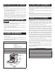
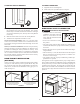
Access the range electrical terminal block by removing the screw
attaching the rear access cover on the back of the range. See Figure 6.
TERMINAL BLOCK AND CHASSIS LOCATION
FIGURE 6
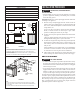
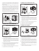
TO CONNECT WITH 4-PRONG POWER CORD
4-PRONG POWER CONNECTION
BLACK WIRE
cut or remove
ground link
GREEN WIRE
WHITE WIRE
RED WIRE
FIGURE 7
1
Thread the power cord and leads through the opening below
the terminal block. See Figure 7.
2
Secure the cord by attaching the strain relief over the cord
insulation jacket. (Strain relief must be placed on the body of
the cord and not on the leads.) Place the strain relief such that
the leads have enough slack to connect to the terminal block
without any stress or tension.
3
Remove the 3 screws from the supply side of the ter minal block.
4
Remove the copper ground link connecting the neutral connec-
tion on the terminal block to the chassis ground.
5
Attach power cord clips with included screws.
6
Attach the power cord leads to the terminal block and chassis.
7
Replace the access cover when complete.
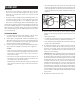
TO CONNECT WITH 3-PRONG POWER CORD
3-PRONG POWER CONNECTION
ground screw
BLACK WIRE
WHITE WIRE
RED WIRE
FIGURE 8
1
Thread the power cord and leads through the opening below
the terminal block. See Figure 8.
2
Secure the cord by attaching the strain relief over the cord
insulation jacket. (Strain relief must be placed on the body of
the cord and not on the leads.) Place the strain relief such that
the leads have enough slack to connect to the terminal block
without any stress or tension.
3
Remove the 3 screws from the supply side of the ter minal block.
4
Attach the power cord leads to the terminal block.
5
Attach power cord clips with included screws.
6
Replace the access cover when complete.
TO CONNECT WITH CONDUIT
cut or remove
ground link
BLACK WIRE
GREEN WIRE
WHITE WIRE
RED WIRE
1
1
/8" conduit
1
3
/8" cord
FIGURE 9
1
Remove and ip the conduit plate below the ter minal block such
that the smaller of the two holes is centered over the opening in
the electrical enclosure. See Figure 9.
2
Insert the conduit strain relief into the opening below the
terminal block. Tighten nut to hold conduit strain relief in place.
3
Thread the conduit leads through the opening and strain relief.
4
Tighten screws on strain relief to secure conduit in place. Place
the conduit within the strain relief such that the leads have
enough slack to connect to the terminal block without any
stress or tension.
5
Remove the 3 screws from the supply side of the ter minal block.
Attach the conduit leads to the terminal.