UX-465L/C UX-485LU SERVICE MANUAL No. 00ZUX465L/SME FACSIMILE UX-465L UX-465 MODEL UX-485 open SELECTION CODE UX-465L (Open LCR) UX-465C UX-485LU LCR www.OpenLCR.com Illustration: UX-465L DESTINATION U.S.A. Canada L.A.G. (120V) CONTENTS CHAPTER 1. GENERAL DESCRIPTION [1] Specifications ............................................ [2] Operation panel......................................... [3] Transmittable documents .......................... [4] Installation .......................................
UX-465L/C UX-485LU CAUTION FOR BATTERY REPLACEMENT (Danish) ADVARSEL ! Lithiumbatteri-Eksplosionsfare ved fejlagtig håndtering. Udskiftning må kun ske med batteri af samme fabrikat og type. Levér det brugte batteri tilbage til leverandoren. (English) Caution ! Danger of explosion if battery is incorrectly replaced. Replace only with the same or equivalent type recommended by the equipment manufacturer. Discard used batteries according to manufacturer’s instructions.
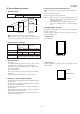
UX-465L/C UX-485LU CHAPTER 1. GENERAL DESCRIPTION [1] Specifications Automatic dialing: (UX-465L) Rapid Key Dialing: 4 numbers Speed Dialing: 40 numbers Scanning method: (UX-465C/485LU) Sheet-feeder CIS (Contact Image Sensor) Automatic dialing: (UX-465C/485LU) Rapid Key Dialing: 5 numbers Speed Dialing: 40 numbers Input document size: Imaging film: Initial starter roll (included with machine): 32 ft. (10 m)(approx. 30 letter-size pages) Automatic feeding: Width 5.8 to 8.
UX-465L/C UX-485LU [2] Operation panel 1 2 3 4 5 6 78 910 FACE DOWN (MAX 10 SHEETS) TEL FAX TAD ABC 1 GHI 2 JKL 4 PQRS 3 MNO 5 8 REPEAT REDIAL RECEPTION MODE VOLUME DOWN UP RESOLUTION FUNCTION REC/MEMO PLAY/SKIP DELETE 6 WXYZ TUV 7 SPEED DIAL DEF HOLD/ SEARCH COPY/HELP 9 STOP 01 SPEAKER 02 03 04/POLL OpenLCR 0 OpenLCR START/MEMORY 11 12 13 14 15 16 17 18 19 20 Illustration: UX-465L 1.
UX-465L/C UX-485LU [3] Transmittable documents 5. Automatic Document Feeder Capacity 1. Document Sizes Number of pages that can be placed into the feeder at anytime is as follows: Normal size width 5.8" - 8.5" (148 – 216 mm) Normal size: max. ADF 10 sheets length 5.5" - 11" (140 – 279 mm) Special size: single sheet only (manual feed) NOTES: (Max.) (Max.) Letter size (Min.) • 600mm 6.
UX-465L/C UX-485LU 7. Use of Document Carrier Sheet TELEPHONE JACK A document carrier sheet must be used for the following documents. • Those with tears. A standard telephone jack must be located near the machine. This is the telephone jack commonly used in most homes and offices. • Those smaller than size 5.8" (W) x 5.5" (L) (148mm (W) x 140mm (L)). • Carbon-backed documents • Make print straight across paper E.G. Place the document carrier in the document feeder with the clear film side down 2.
UX-465L/C UX-485LU 4 Remove the used film from the cartridge. 9 Cut the band that holds the two spools together. Unroll the film slightly and insert the small gears into their holders. 5 Remove the four green gears from the used film. DO NOT DISCARD THE FOUR GREEN GEARS! F Turn the cartridge over, grasp the handle, and insert the cartridge into the print compartment. 6 Remove the new roll of imaging film from its packaging. • Do not yet remove the band that holds the rolls together.
UX-465L/C UX-485LU 3. Assembly and connections (UX-465L ONLY) 1. Press these keys : 1 Plug the power cord into a 120V, 60Hz, grounded(3-prong) AC out• 4 The display will show: DIAL MODE let. • FUNCTION Caution: Do not plug the power cord into any other kind of outlet. This will damage the machine and is not covered under the warranty. TONE 2. Press 1 to select tone dialing, or 2 to select pulse dialing.
UX-465L/C UX-485LU 2 Pull the paper release plate toward you. 5 The fax has been set at the factory to scale the size of received faxes to letter size paper. If you have loaded legal paper, you must change the paper size setting to legal. Press these keys: FUNCTION (UX-465L/C) The display will show: PAPER SIZE SET 6 LETTER Press 1 to select LETTER, 2 to select LEAGAL. 1 LEAGAL 2 or The display will show: COPY CUT-OFF STOP Press the STOP key to return to the date and time display.
UX-465L/C UX-485LU 2 Remove the document. 3 Gently pull the jammed paper out of the machine, making sure no 3 Close the operation panel, making sure it clicks into place. 4 Close the print compartment cover (press down on both sides to make torn pieces of paper remain in the print compartment or rollers. sure it clicks into place), and then close the operation panel. Click! 5 Pull the paper release plate toward you, reinsert the paper in the paper tray and push the paper release plate back down. 6.
UX-465L/C UX-485LU SENDING FAXES [5] Quick reference guide (UX-465L) ENTERING YOUR NAME AND NUMBER FUNCTION 1. Press: 3 Display shows: OWN NUMBER SET Place your document (up to 10 pages) face down in the document feeder. 2. Press: START/MEMORY 3. Enter your fax number (max. of 20 digits) by pressing the number keys. ♦ To insert a space between digits, press the # key. ♦ If you make a mistake, press the SPEED DIAL key to backspace and clear the mistake. 4. Press: START/MEMORY 5.
UX-465L/C UX-485LU [5] Quick reference guide (UX-465C/485LU) Press the START/MEMORY key: START/MEMORY INSTALLATION Enter two digits for the Month (01 through 12). 1 2 Enter two digits for the Day (01 through 31). Enter four digits for the Year (Ex: 2001). Enter two digits for the Hour (01 through 12). TEL. SET Enter two digits for the Minute (00 through 59). TEL. LIN E key for A.M. or the # key for P.M. Press the 3 STOP When finished, press: START/MEMORY 1. Connect the handset as shown.
UX-465L/C UX-485LU CHAPTER 2. ADJUSTMENTS 3. Settings [1] Adjustments DIAL mode (Soft Switch No. SWB4 DATA No. 3) (1) Dial mode selector (step 1) Select "OPTION SETTING". General KEY : FUNCTION Since the following adjustments and settings are provided for this model, make adjustments and/or setup as necessary. DISPLAY: OPTION SETTING 4 PRESS OR # (step 2) Select "DIAL MODE". 1. Adjustments KEY: Push # until " DIAL MODE " is indicated because the number of # s changes by the model.
UX-465L/C UX-485LU [2] Diagnostics and service soft switch 1. Operating procedure (1) Entering the diagnostic mode Press FUNC → 9 → ROM Ver. FQM0 → 8 → # → 7 , and the following display will appear. (FQN0 , FQP0 ) After 2 sec: DIAG MODE FQM0 (UX-465L) FQN0 (UX-465C) FQP0 (UX-485LU) Then press the START key. Select the desired item with the key or the # key or select with the rapid key. Enter the mode with the START key.
UX-465L/C UX-485LU 3. Diagnostic items description 3. 1. Soft switch mode 3. 6. Signal send mode This mode is used to send various signals to the circuit during FAX communication. Every push of START key sends a signal in the following sequence. Moreover, the signal sound is also output to the speaker when the line monitor of the soft switch is on. Used to change the soft switch settings. The soft switch which is stored internally is set by using the keys. The available soft switches are SW-A1 to SW-N3.
UX-465L/C UX-485LU 3. 12. Entry data receive 3. 13. Message print (UX-485LU only) In this mode, the registered data sent from the other machine is received and the received data is registered in the machine. When this mode is used for receiving, the other machine must be in the entry data send mode. In this mode, all the message data, which are used for displaying indication and list print, are printed as a contrast table of the selected language and English.
UX-465L/C UX-485LU 5. Soft switch description • Soft switch SW NO. SW l A1 DATA NO.
UX-465L/C UX-485LU SW NO. SW l A6 DATA NO.
UX-465L/C UX-485LU SW NO. DATA NO. 1 Switch setting and function ITEM 1 DTMF signal transmission level (High) 2 SW l B6 No. = Binary input 0 16 8 4 2 1 0 1 2 3 4 5 0 0 1 1 1 1 1 3 4 5 6 Dial tone detection (LCR center call) (UX-465L only) 7 8 Reserved Reserved No Yes 0 0 0 Factory Light Dark setting 0 1 0 1 0 2 No. 2 0 Factory 0 Light 1 Dark 1 Darker in 0 setting 3 dark No. 3 0 1 0 1 0 No.
UX-465L/C UX-485LU SW NO. SW l E1 SW l E2 SW l E3 Switch setting and function DATA NO. ITEM 1 Tel/Fax Automatic switching mode (UX-485LU only) 2 Pseudo ringing time at phone/fax automatic switching mode (UX-485LU only) 3 4 Number of CNG signal detection at the tel/ 1 Tel/Fax auto switch No.
UX-465L/C UX-485LU SW NO. SW l G2 SW l G3 DATA NO. Switch setting and function ITEM 1 1 2 Reserved Reserved 0 0 3 4 Reserved Reserved 0 0 5 Reserved 0 6 Reserved 0 7 Reserved 0 8 Reserved 0 1 Reserved 0 2 Reserved 0 3 Reserved 0 4 Reserved 0 5 Reserved 0 6 Reserved 0 7 Reserved 0 8 Reserved 1 150ms duration) 2 200ms 250ms 350ms No. 1 0 0 1 1 0 No.
UX-465L/C UX-485LU SW NO. DATA NO. 1 SW l I2 SW l I3 A.M. quiet detect time Binary input 8 4 2 1 1 2 3 4 5 1 4 5 0 0 1 1 0 1 0 CPC detection time (UX-465L/C only) 4ms 20ms 40ms 70ms 140ms 160ms 200ms 290ms No. 6 0 0 0 0 1 1 1 1 1 7 No. 7 0 0 1 1 0 0 1 1 1 8 No.
UX-465L/C UX-485LU SW NO. SW l J1 DATA NO. Switch setting and function ITEM 1 No printout when memory full 0 2 Total communication hours and pages print No Yes 0 3 4 Sender’s phone number setting Reserved Cannot change Change allowed 0 0 5 Reserved 6 Summer time setting (UX-465L/C only) No Yes 1 0 1 Reserved 2 Reserved 3 Polling key Off Low Middle High No. 7 0 0 1 1 1 No. 8 0 1 0 1 0 OPTION 0 Yes No Handset receiver volume (UX-465L/C only) 4 No. 4 5 No.
UX-465L/C UX-485LU SW NO. DATA NO. Switch setting and function ITEM 1 0 Paper set size 1 2 SW l L2 SW l M1 SW l M2 3 4 Automatic reduce of receive Print contrast OPTION LEGAL A4 0 0 1 0 No.
UX-465L/C UX-485LU SW-A2 No. 8 CNG transmission • Soft switch function description When set to "0" , this model allows CNG transmission by pressing the Start key in the key pad dialing mode. When set to "1", CNG transmission in the key pad dialing mode cannot be performed. In either case. CNG transmission can be performed in the auto dial mode. SW-A1 No. 1 Protect from echo Used to protect from echo in reception. SW-A1 No. 2 Forced 4800BPS reception SW-A3 No. 1, No.
UX-465L/C UX-485LU SW-B2 No. 7, No. 8 Reserved SW-A5 No. 5, No. 6 Digital cable equalizer setting Set to "0". (Reception for Caller ID) Line equalization when reception for CALLER ID is to be set according to the line characteristics. Setting should be made according to distance between the telephone and the telephone company central switching station. SW-B3 No. 1 ~ No. 5 Reserved SW-A5 No. 7 Error criterion Delay time between the dial key input and line connection under the auto dial mode.
UX-465L/C UX-485LU SW-B6 No. 6 Dial tone detection (LCR center call) (UX-465L only) Used to set YES/NO of dial tone detection (calling LCR center). Phone Number Intended Purpose SW-B6 No. 7, No. 8 Reserved Ring Pattern Set to "0". SW-C1 No. 1, No. 2 Reading slice (Binary) Used to determine the set value of reading density in standard/fine mode. The standard setting is "00" (Factory setting is "00") SW-C1 No. 3, No.
UX-465L/C UX-485LU SW-D2 No. 4 Reserved SW-F1 No. 1, No. 2 DTMF detect time Set to "0". Used to set detect time of DTMF (Dual Tone Multi Frequency) used in remote reception (5 ). SW-D2 No. 5 Caller ID function The longer the detect time is, the less the error detection is caused by noises. Used for Caller ID function. SW-D2 No. 6 Caller ID detect during CI off SW-F1 No.
UX-465L/C UX-485LU SW-H1 No. 3, No. 4 Busy tone detection ON/OFF time (Upper duration) SW-I1 No. 3, No. 4 A.M. quiet time 1 Used to select four kinds of no sound time (2 sec ~ 5 sec) after reception in the T.A.D mode until OGM is output. Similarly to SW-H1 No. 1, the set value can be varied. The upper limit can be set in the range of 650msec to 2700msec. Reception OGM output ICM recording SW-H1 SW-H1 SW-H1 SW-H1 No. 1 No. 2 No. 3 No.
UX-465L/C UX-485LU SW-J2 No. 1, No. 2 Reserved SW-I5 No. 5 ~ No. 8 AGC eref access code (Mic) (-0 ~ -30dB) (2dB step) Set to "0". The AGC Energy Reference Level controls the playback level. Any message having average speech energy above the energy reference level has its playback level attenuated, and any level has its playback level increased. If the playback level is too high (low), then decreasing (increasing) the AGC energy Reference level will achieve the desired level. SW-J2 No.
UX-465L/C UX-485LU SW-L2 No. 5 Reception reduction ratio in case of memory full This model is designed so that the print is started according to the setting of SW-L2 No.3 when reception of one page is completed. However, if the memory is filled with data before completion of reception of one page, the print is started with the reduction ratio which is set with this switch. SW-L2 No. 6 ~ No. 8 Reserved Set to "0". SW-M1 No. 1 ~ No. 8 Reserved Set to "0". SW-M2 No. 1 ~ No. 8 Reserved Set to "0". SW-N1 No.
UX-465L/C UX-485LU [3] Troubleshooting Refer to the following actions to troubleshoot any of the problems mentioned in 1-4. [1] A communication error occurs. [2] Image distortion produced. [3] Unable to do overseas communication. [4] Communication speed slow due to FALLBACK. • Increase the transmission level SOFT SWITCH A4-1, 2, 3, 4, 5. May be used in case [1] [2] [3]. • Decrease the transmission level SOFT SWITCH A4-1, 2, 3, 4, 5. May be used in case [3].
UX-465L/C UX-485LU [4] Error code table 1. Communication error code table G3 Transmission Code Final received signal Error Condition (Receiver side) 0 Incomplete signal frame Cannot recognize bit stream after flag 1 NSF, DIS Cannot recognize DCS signal by echo etc.
UX-465L/C UX-485LU MEMO 2 – 22
UX-465L/C UX-485LU 3-2. Automatic document feed CHAPTER 3. MECHANISM BLOCKS 1) Use of the paper feed roller and separation rubber plate ensures error-free transport and separation of documents. The plate spring presses the document to the paper feed roller to assure smooth feeding of the document. [1] General description 2) Document separation method: Separation rubber plate 1.
UX-465L/C UX-485LU Separation rubber 5. Recording block Last page of document (1) General view ,,,,,,,,,, ,,,,,,,,,, ,,,,,,,,,, ,,,,,,,,,, ,,,,,,,,,, ,,,,,,,,,, ,,,,,,,,,, ,,,,,,,,,, ,,,,,,,,,, Back of document RP release plate First page of document Platen roller PO roller Paper feed spring PU roller Pinch roller Paper feed roller Rotation plate PO gude Fig. 4 Film cartridge RP hopper 3-5. Documents requiring use of document carrier 1) Documents smaller than 148mm (W) x 140mm (L).
UX-465L/C UX-485LU [2] Disassembly and assembly procedures • • This chapter mainly describes the disassembly procedures. For the assembly procedures, reverse the disassembly procedures. • • The numbers in the illustration, the parts list and the flowchart in a same section are common to each other. Easy and simple disassembly/assembly procedures of some parts and units are omitted. For disassembly and assembly of such parts and units, refer to the Parts List.
UX-465L/C UX-485LU Parts list (Fig. 2) PWB’s, drive unit, AC cord ass’y and speaker 2 No. Q’ty No.
UX-465L/C UX-485LU 3 Paper roller etc. and sensor lever Parts list (Fig. 3) No. Q’ty No.
UX-465L/C UX-485LU 4 Drive frame Parts list (Fig. 4) No. Q’ty No. Q’ty No.
UX-465L/C UX-485LU 5 Sub frame unit, original paper guide, operation panel unit and CIS unit Parts list (Fig. 5) No. Q’ty No.
UX-465L/C UX-485LU 6 Upper cabinet and document guide upper unit Parts list (Fig. 6) No. Q’ty No. 1 Screw (3×8) Part name 2 7 Operation panel PWB 2 Document guide upper 1 8 Direct key 1 9 Mode key 1 unit Part name Operation panel unit 1 10 Stop key 1 4 Screw (2×6) 5 11 Start key 1 5 Cable 1 12 12 key 1 6 Insulation sheet 1 13 TAD Key 1 14 Upper cabinet 1 2 Note) Keep the document guide upper unit in the rib of operation panel unit like the picture.
UX-465L/C UX-485LU 7 Document guide upper Parts list (Fig. 7) No. Q’ty No.
UX-465L/C UX-485LU Sub frame, top cover unit RP hopper unit 8 Parts list (Fig. 8) No. 1 2 3 4 5 6 7 10 11 12 13 14 15 26 27 16 17 18 Q’ty No. Q’ty No.
UX-465L/C UX-485LU 9 Top cover and RP hopper Parts list (Fig. 9) No. Q’ty No.
UX-465L/C UX-485LU 10 Parts list (Fig. 10) Thermal head No. 1 2 3 4 5 6 7 8 9 10 11 12 13 14 15 16 Q’ty No.
UX-465L/C UX-485LU 11 Wire treatment Parts list (Fig. 11) No. Panel cable Document guide upper unit Part name Screw (3×10) 2 Screw (4×6) 1 1 3 Core (F2125) 1 4 Screw (3×6) 1 5 Screw (3×6) 1 The Head cable and Head earth cable pass to the core 2 times.
4–1 EXT.TEL LINE HANDSET SPEAKER DRAM 4Mbit SPEAKER AMPLIFIER SURGE PROTECT/ FILTER AMPLIFIER AMPLIFIER CML AMPLIFIER INTEGRATED ANALOG DEVICE (20415) FLASH MEMORY 4Mbit CONTROL PWB UNIT [1] Block diagram CI TRANSFORMER AMPLIFIER CLOCK 32.256MHz BZ TEL/LIU PWB UNIT CLOCK 32.768kHz VBT +3.
FG FG 4–2 14 OPERATION PANEL PWB NUIT CNLCD LCD UNIT CNPN CONTACT IMAGE SENSOR THERMAL HEAD [2] Wiring diagram 15 7 16 CNCIS CNTH TX/RX MOTOR CNPN CNMT 6 SPEAKER 2 CNSP CONTROL PWB UNIT CNCSW 2 CAM SW CNPW CNLIUA FG 8 14 ARG POWER SUPPLY PWB UNIT CN1 CNLIUA TEL/LIU PWB UNIT CNLNJ/TLJ MJTEL 4 FG TEL LINE EXTERNAL LINE HANDSET AC CORD UX-465L/C UX-485LU
UX-465L/C UX-485LU [3] Point-to-point diagram CNMT TX/RX MOTOR THERMAL HEAD OPERATION PANEL PWB CIS TPBD TPAD TPBD TPAD VMT VMT VTH VTH STRB1 STRB2 THI N.C. THG THG THG THVDD STRB3 STRB4 LATCH PCLK DATA VTH 1 2 3 4 5 6 1 2 3 4 5 6 7 8 9 10 11 12 13 14 15 16 CNPN 1 KEN4A 2 KEN3A 3 KEN2A 4 KEN1A 5 +3.
UX-465L/C UX-485LU 3. Operational description CHAPTER 5. CIRCUIT DESCRIPTION Operational descriptions are given below: • [1] Circuit description When a document is loaded in standby mode, the state of the document sensor is sensed via the 1 chip fax engine (SCE114V). If the sensor signal was on, the motor is started to bring the document into the standby position. With depression of the START key in the offhook state, transmission takes place.
UX-465L/C UX-485LU 3) 27L2000 (IC7): pin-32 DIP (ROM) [2] Circuit description of control PWB ROM of 2Mbit equipped with software for the main CPU. 1. General description 4) W24L257S-70LL (IC2): pin-28 SOP (SRAM) Fig. 2 shows the functional blocks of the control PWB, which is composed of 5 blocks. Line memory for the main CPU system RAM area and coding/decoding process. Used as the transmission buffer. MAIN CONTROL BLOCK Memory of recorded data such as daily report and auto dials.
UX-465L/C UX-485LU SCE114V (IC10) Terminal descriptions Pin No.
UX-465L/C UX-485LU SCE114V (IC10) Terminal descriptions Pin No.
UX-465L/C UX-485LU SCE114V (IC10) Terminal descriptions Pin Pin List No.
UX-465L/C UX-485LU (2) Panel control block The following controls are performed by the SCE114V.
UX-465L/C UX-485LU (4) Modem (SCE114V/20415) block 4. FEATURES The modem block consists of two parts. One is SCE114V Fax Modem DSP Core and the other is 20415 Integrated Analog Device. • 1. FACSIMILE MODEM The modem can operate at 14400, 12000, 9600, 7200, 4800, 2400, or 300 bps, and can perform HDLC framing per T.30 at all rates. A programmable DTMF detector, three programmable tone detectors, V.21 Channel 2 FSK 7E flag detector, Caller ID demodulator and ring detector are provided. 2.
UX-465L/C UX-485LU [3] Circuit description of TEL/LIU PWB (1) TEL/LIU block operational description 20415 INTEGRATED ANALOG DEVICE 1) Block diagram TEL/LIU PWB SP OUT ENABLE CONTROL PWB W-TONE TXOUT RTLOOP SPKRP-P L1 CML M C L2 MIC ENABLE SIN DAC SP DRIVER TXMUTE B (0:1) (1:0) (0:0) (1:1) DAC GAIN 0,6dB CI MIC GAIN MICP RXIN MIC IN LPF 0 0,20,25,30dB UX-465L/C ONLY TELIN MIC 1 ENABLE ADC LINEIN LINE IN LPF LINE IN 1 ENABLE SOUT ADC GAIN 0,–4dB 0 HANDSET VOL_A RX RCV VOL TELM
UX-465L/C UX-485LU 5. Externally connected TEL OFF HOOK detection circuit section • 4) Signal selection The following signals are used to control the transmission line of TEL/ FAX signal. For details, refer to the signal selector matrix table. The circuit current detection is turned on together with OFF HOOK of main body or OFF HOOK of externally connected TEL. ON of CML OFF (HS=L) is judged as OFF HOOK of externally connected TEL. [Control signals from output port] Signal Name 6.
UX-465L/C UX-485LU [Signals for status recognition according to input signals] NO Signal Name (CNLIUA) NO 1 TELOUT 8 RHS H:The handset is in the on-hook state. 2 TELMUTE 9 RXIN L: The handset is in the off-hook state.
UX-465L/C UX-485LU [4] Circuit description of power supply PWB 1. Block diagram 2.5A/125V AC IN Noise Filter Circuit Rectifying Smoothing Circuit Switching Circuit (RCC system) Regulator Circuit +5V +24V FUSE 4A/72V Control Circuit Photo Coupler Fig. 8 2-1. Noise filter circuit 2-4. Control circuit The input noise filter section is composed of L1 and C1, which reduces normal mode noise from the AC line and common mode noise to the AC line.
6–1 A 1 2 3 4 1 2 3 4 L105 0 R197 8 470 1 7 2 3 6 4 5 8 7 6 5 TPA TPB TPA TPB 8 7 6 5 R142 120 C154 C221 SEN5 SEN6 SEN7 C222 C223 (5-5E) (5-5E) (5-5E) (5-5E) C109 1000P C110 1000P C111 1000P C120 1000P KEN1A KEN2A KEN3A KEN4A CNPN-4 CNPN-3 CNPN-2 CNPN-1 E SEN4 SEN0 SEN1 SEN2 SEN3 CNPN-14 CNPN-15 CNPN-13 CNPN-12 CNPN-11 CNPN-10 C156 C136 C137 C138 C155 CNPNB-5 CNPNB-3 E C102 C112 C113 C114 F (5-6D) (5-2H) D 66 BZOUT1 BZOUT2 C VIN THADI DG C186 22P B 169 SM0 168 SM1 167 SM2 166
6–2 1 2 3 4 5 6 (1-3I) (1-3I) A (1-6I) (1-5I) RD ROMCS R128 10K +3.3V D[7~0] A[18~0] A17 A18 A0 A1 A2 A3 A4 A5 A6 A7 A8 A9 A10 A11 A12 A13 A14 A15 A16 Memory block A N.M. R127 B B 22 31 12 11 10 9 8 7 6 5 27 26 23 25 4 28 29 3 2 30 @ @ CE A0 A1 A2 A3 A4 A5 A6 A7 A8 A9 A10 A11 A12 A13 A14 A15 A16 A17 A18 16 32 1 13 14 15 17 18 19 20 21 OE 24 GND VCC VPP D0 D1 D2 D3 D4 D5 D6 D7 IC7 27L2000 ROM DG C C134 0.1 +3.3V C (4-1C) (1-3I) (1-3I) CE2 N.M.
6–3 1 2 3 4 5 6 A (6-1I) (6-1I) (6-1I) (5-4E) (2-1G) CNLIUB-1 CNLIUB-3 CNLIUA-15 (5-5E) CNLIUA-2 CNLIUA-11 (5-1A) (4-5C) CNPW-9 (2-1G) (2-2G) (2-2G) (2-2G) (2-1G) (4-4C) (4-4C) (4-5C) (4-6C) CNLIUB-2 CNLIUB-4 CNLIUA-16 CNLIUB-5 (6-1A) (6-4H) CNLIUA-5 CNLIUA-6 CNLIUA-7 CNLIUA-8 CNLIUA-4 (6-3A) (6-1D) FCS1 VOL-A VOL-B VOL-C VTHON RLYCONT DPON LEDON TELMUTE CML PNLON RBNSNS PSAVE FRSNS FRD FWR FCLE FACE READY ORGSNS DRSNS CSWI DPMUTE DPMUTE ERLY TXMUTE RCVOL SPMUTE
6–4 1 2 3 4 5 6 B A CNPN-9 CNPN-8 +5V CNCSW-1 1 ORGSNS (1-6G) FRSNS 2 3 RESETO C215 +3.3V R206 220 SW1 COVER SW <+5V> DG CSW B R203 10K DG R204 1 R129 270 R112 270 N.M. OUT GND 2 R105 270 DG B DG DRSNS C R202 4.7K DG E (3-3A) (3-3A) (3-2A) (3-4A) (3-4A) CE2 PWRDWN Q108 2SC2412K C119 100P C N.M. FRSNSI R227 +3.3V ORGSNSI N.M. RBNSNS R226 +3.3V C118 100P DG 4 3 CSWI C R225 DG C126 100P R224 +3.3V N.M. +3.3V N.M.
6–5 1 2 3 4 5 6 B C A (3-2A) (5-5H) +24V +3.3V CNCIS-1 PNLON R103 10K VG R102 30 LEDON VO B B DG E Q109 C E C R212 R211 C105 0.1 +5V DG +24V CNCIS-6 C N.M. 1 3 VIN VG CISVDD CNCIS-7 Q110 2 GLED C103 0.1 C184 0.01 Q100 KTA1504GR L100 0 VG DG C1 220/6.3 B R104 5.1K CISVDD D R213 0 D +5V CNCIS-2 CNCIS-3 (1-1F) Video processing/Motor driver / Thermal block A CNPN-7 (3-1A) E E +3.
6–6 1 2 3 4 5 6 B (3-5A) CNLIUA-9 (3-6A) CNLIUA-10 CNMIC-3 CNMIC-2 CNMIC-1 CNLIUA-1 A DG RCVOL RXIN B R181 N.M. R166 0 DG DG E C C204 0.1 R165 0 R201 100K DG B DG 4 + – R184 11K 2 3 8 DG R199 4.7K DG R169 IC12 1 C193 R167 0 C DG E B Q104 KRC102S C201 0.1 N.M. C (3-2A) D106 SIGTX IC12 C171 0 W-TONE N.M. DG C220 + – C192 0 C (3-3H) Q101 R170 N.M.
UX-465L/C UX-485LU Control PWB parts layout (Top side) 6–7
UX-465L/C UX-485LU Control PWB parts layout (Bottom side) 6–8
6–9 1 2 3 4 5 6 B TLJ-1 CNLNJ-5 CNLNJ-4 CNLNJ-3 CNLNJ-2 TLJ-2 A JP4 N.M. JP2 AR2 RA-391P-V6-2 EX-L1 L2 L1 EX-L2 JP5 JP3 JP6 B N.M. JP7 JP10 L1 B L1 L1 A JP11 N.M. [2] TEL/LIU PWB circuit A N.M. JP8 N.M. L3 N.M. AR1 VA2 ERZV5D471 JP9 L2 ARG N.C. VA1 ERZV5D471 C C C C B M CML2B N.M. M B N.M. CML 2A C M B CML1 OUAZ-SH-124DZ N.M. L7 C101 JP12 C4 0.82 D R6 30 R4 91 ZD3 HZ2C1 N.C. N.C.
6 – 10 1 2 3 4 5 6 B A MJTEL1-3 MJTEL1-2 CNHJ-1 CNHJ-4 (1-5I) C100 2200P RX- RX+ TX- TX+ +5V C115 1 IN/OUT JP15 L6 L5 JP13 N.M. L4 JP14 N.M. B D3 C9 22/50 +5V C105 0.1 DG C111 1000P DG R110 150 C DG R139 3.3K C120 1000P DG DG R136 0 1 ZD7 IC101A NJM2904M R125 43K R123 N.M. N.M. C10 6 + 5 – R130 86.6K C114 33P D 7 C D DG E B Q104 DTC143ZK R129 4.7K R126 0 – 6 + 5 R140 220K C119 220P +5VA IC101B NJM2904N DG R127 3.3K IC102B NJM2904M N.
6 – 11 1 2 3 4 5 6 B A DG SW1 +5V B +24V R120 R119 TEL/LIU PWB circuit A PC1 PC814X PC4 CML2 N.M. CML1 OUAZ-SH-124DZ D2 1SS133 DG DG DG PC5 TLP521 N.M. PC3 N.M. PC2 C C C C113 1000P C109 N.M. N.M. N.M.
UX-465L/C UX-485LU TEL/LIU PWB parts layout (Top side) 6 – 12
UX-465L/C UX-485LU TEL/LIU PWB parts layout (Bottom side) 6 – 13
A N.M. C19 6 – 14 2 B C3 470P C2 150/200 C7 4700P Q3 2SC1740S 1 CN2 F1 2.5A/125V V1 ERZV07D241-CS C18 L1 D4 ERA15-06 D2 ERA15-06 R9 470 C R10 0.15(1/2W) R8 47K ZD1 N.M. Q1 FS5KM-14 C Q2 2SC1741AS QR C5 4700P C17 1000P D E E D5 1SS133 PC1 PS2501-1L R6* 47K R7 180 R4 330 R5 5.6K C22 330P C4 2200P R6*: Adjustment Resistor R23 100 C20 1500P R3 180K R2 820K D ZD2 RD4.3ESAB2 T1 PTTN103 FB1 C11 0.1 F ZD5 RD6.2ESAB2 R18 1.
UX-465L/C UX-485LU F3 Power supply PWB parts layout 6 – 15
6 – 16 C1 22/50 16 11 12 13 1 2 3 4 5 10 +5V GND 8 VCC D1 D2 D3 D4 D5 D6 D7 D8 D9 DG +3.3V DG C3 22000P +3.3V REPEAT DELETE RECEPTION RESOLUTION DG STOP PLAY DOWN R1 6.
UX-465L/C UX-485LU CHAPTER 7.
UX-465L/C UX-485LU [2] Power on sequence START CPU initialized MODEM initialized “WAIT A MOMENT” display STOP key ? NO “MEMORY CLEAR ?” display NO 3 sec ? YES 1 YES STAND-BY START key ? NO 2 YES COPY key ? 1 2 “MEMORY CLEARED” display “MEMORY CLEARED” display Memory clear Memory clear STAND-BY PROCESS CHECK MODE NO YES STOP key ? NO 3 sec ? NO YES STAND-BY 7–2
UX-465L/C UX-485LU CHAPTER 8. OTHERS [1] Service tools 1. List NO.
UX-465L/C UX-485LU 2. Description 2-1. Relay board unit 1. Remove the TEL/LIU PWB, control PWB and Power Supply PWB from this unit, and mount the relay board unit instead. • Before connecting the wiring to the relay board unit, set the test PWB switches to the fixed position. 2. The setting is as follows. • The relay cables are used as one pair. • The cover swtich and hook switch are manually operated. • The recording paper sensor(P-E) is not used.
UX-465L/C UX-485LU 3. Shading paper The white and black basis is applied to remember the shading waveform. Be sure to perform this operation when replacing the battery or replacing the control PWB. Execute in the shading mode of DIAG mode.
UX-465L/C UX-485LU [2] IC signal name CONTROL PWB UNIT IC4: VHiKiD65001AP (KID65001AP) IC2: VHiW24L257S7L (W24L257S-70LL) (TOP VIEW) O1 O2 O3 O4 O5 O6 O7 COM 16 15 14 13 12 11 10 9 A14 1 28 VDD A12 2 27 WE A7 3 26 A13 A6 4 25 A8 A5 5 24 A9 A4 6 23 A11 A3 7 22 CS2/OE A2 8 21 A10 Pin name Signal 20 CS1 A0~A14 CS1/CS2 Address input A1 1 I1 2 I2 3 I3 4 I4 5 I5 6 I6 7 8 I7 GND 9 A0 10 19 IO8 IO1 11 18 IO7 IO2 12 17 IO6 IO3 13 16 IO5 VSS 14 15 IO4 WE OE I/O1~I/O
UX-465L/C UX-485LU IC10: VHiSCE114V/-1 (SCE114V) GPIO[31] GPIO[32] GPIO[33] GPIO[34] GPIO[35] GPIO[36] VDD GPIO[0]/SR4IN GPO[31]/SR3OUT GPIO[37]/IRQ15N IARESET IACLK/DSPCSN IA1CLK SR3IN/DSPIRQN SR4OUT SR1IO SA1CLK VSSPLL TSTCLK DEBUGN RDN WRN SYNC/GPO[20] ROMCSN CS1N/GPO[21] VSS SXIN SXOUT VDD PM[3]/GPO[3] PM[2]/GPO[2] PM[1]/GPO[1] PM[0]/GPO[0] SM[3]/GPO[7] SM[2]/GPO[6] SM[1]/GPO[5] SM[0]/GPO[4] REGDMA/GPO[18] WAITN/GPO[19] VDDPLL D[7] D[6] D[5] D[4] 133 134 135 136 137 138 139 140 141 142 143 144 145 146
UX-465L/C UX-485LU [3] Changing the record paper size (UX-465L/C only) How to change the A4 size and letter size of the record papers 1) It becomes the record paper of the A4 size by installing A4 guide (PGiDM2535XHSC) which shows in the drawing. Remove A4 guide when you use the record paper of the letter size. Record paper hopper A4 Guide PGiDM2535XHSC 2) Set soft switch SW-L2 No.1 and the initialization of SW-L2 No.2 as follows. SW NO. DATA NO.
UX-465L/C UX-485LU MEMO 8–7
UX-465L/C UX-485LU PARTS GUIDE UX-465L UX-465 MODEL UX-485 SELECTION CODE UX-465L (Open LCR) UX-465C UX-485LU DESTINATION U.S.A. Canada L.A.G. (120V) CONTENTS 1 Cabinet, etc.
UX-465L/C UX-485LU [1] Cabinet, etc.
UX-465L/C UX-485LU NO. PARTS CODE PRICE RANK NEW MARK PART RANK BE N N N E E E C C C C C C C C D D D C C C C C C C C C C C C C C C C C C C C C B C C C B E E E E C C C B C B C D D C C E C C C C C C C C C C C C C DESCRIPTION [1] Cabinet,etc.
UX-465L/C UX-485LU [2] Top cover and sub frame 27 33 35 24 29 B2 B2 25 21 31 28 B2 12 30 11 2 26 18 19 17 15 1 8 7 34 8 B2 7 9 5 B2 12 3 4 32 B6 20 23 13 10 6 22 14 PARTS CODE NO.
UX-465L/C UX-485LU [3] Upper cabinet 901 1 2 13 8 6 7 12 B1x3 3 10 4 5 9 11 NO.
UX-465L/C UX-485LU [4] Document guide upper 2 6 1 5 10 13 8 15 7 16 4 11 4 9 9 12 NO.
UX-465L/C UX-485LU [5] Drive unit 18 B2 16 12 29 28 13 11 30 1 7 24 14 19 15 21 22 20 27 6 24 17 25 23 24 26 9 PARTS CODE NO.
UX-465L/C UX-485LU [6] Packing material & Accessories 18 16 17 15 16 14 13 16 19 TAPE 12 10 TAPE 27 25 26 TAPE 1 TAPE 29 AC CORD 7 11 4 30 3 2 R 31 32 TAPE 8 MARK"A" 24 TAPE 1 9 (1) (3) 28 23 (2) 5 22 (4) 21 6 R –7– TAPE
UX-465L/C UX-485LU NO.
UX-465L/C UX-485LU NO.
UX-465L/C UX-485LU NO.
UX-465L/C UX-485LU PARTS CODE NO.
UX-465L/C UX-485LU NO.
UX-465L/C UX-485LU PARTS CODE NO.
UX-465L/C UX-485LU Index PARTS CODE [C] CCNW-4938XH01 CGERH2444XHY1 CGERH2459XH01 CLEVP2298XH01 CLEVP2299XH01 CLEVP2300XH01 CLEVP2303XH01 CPLTP3002XHB1 CPLTP3002XHB3 CPLTP3002XHB4 CROLR2434XH01 [D] DCEKC584PXHZZ ″ DCEKC687PXHZZ ″ DCEKC886PXHZZ ″ DCEKL254CXH06 ″ DCEKP253CXH13 ″ DCEKP253CXH17 ″ DCEKP253CXH22 ″ DCEKP255CXH04 ″ DUNTK369BXHLW DUNTK464BXHBG DUNTK464BXHLW [G] GCABA2365XHSJ GCABA2365XHSM GCABA2365XHSQ GCABB2325XHSH GCABB2325XHSJ GCABB2325XHSM GCOVA2403XHYE GCOVA2403XHYS GLEGG2068XHZZ [H] HPNLH2391
UX-465L/C UX-485LU PARTS CODE [T] TCADH3090XHZZ TCADZ2889XHZZ TCADZ2891XHZZ TCADZ3045XHZZ TCADZ3142XHZZ TCADZ3167XHZZ TCADZ3168XHZZ TINSE4176XHTZ TINSK4189XHTZ TINSS4204XHTZ TLABH212AXHZZ TLABH220AXHZZ TLABH447BXHZZ TLABH4751XHZZ TLABH4752XHZZ TLABH480AXHZA TLABH4853XHZZ TLABH4936XHZZ TLABH4937XHZZ TLABM342BXHZZ TLABM403CXHZZ TLABM417CXHZZ [U] UBATL2049SCZZ [V] VCCCCY1HH101J ″ ″ ″ ″ ″ ″ ″ ″ ″ ″ ″ ″ ″ ″ VCCCCY1HH150J VCCCCY1HH180J VCCCCY1HH220J ″ VCCCCY1HH221J ″ VCCCCY1HH330J ″ VCEAGA0JW227M ″ ″ VCEAGA1EW47
UX-465L/C UX-485LU PRICE NEW PART RANK MARK RANK PARTS CODE No.
UX-465L/C UX-485LU COPYRIGHT © 2001 BY SHARP CORPORATION ALL RIGHTS RESERVED. No part of this publication may be reproduced, stored in a retrieval system, or transmitted in any form or by any means, electronic, mechanical, photocopying, recording, or otherwise, without prior written permission of the publisher.