UX-108U/178U/188U FO-375U SERVICE MANUAL No. 00ZUX108U/SME FACSIMILE UX-108 UX-178 UX-188 MODEL FO-375 Non Cutter model UX-108 Illustration: UX-108 Cutter model UX-178/188 FO-375 CONTENTS CHAPTER 1. GENERAL DESCRIPTION [1] Specifications ............................................ [2] Operation panel......................................... [3] Transmittable documents .......................... [4] Installation ................................................. [5] Quick reference guide ...............
UX-108U/178U/188U FO-375U CAUTION FOR BATTERY REPLACEMENT (Danish) ADVARSEL ! Lithiumbatteri-Eksplosionsfare ved fejlagtig håndtering. Udskiftning må kun ske med batteri af samme fabrikat og type. Levér det brugte batteri tilbage til leverandoren. (English) Caution ! Danger of explosion if battery is incorrectly replaced. Replace only with the same or equivalent type recommended by the equipment manufacturer. Discard used batteries according to manufacturer’s instructions.
UX-108U/178U/188U FO-375U CHAPTER 1. GENERAL DESCRIPTION [1] Specifications Automatic dialing: Rapid Key Dialing: 10 numbers Speed Dialing: 20 numbers Fax paper: Initial starter roll (included with fax machine): 49 ft. (10 m) roll Recommended replacement roll: FO-40PRw 164 ft. (50 m) roll Automatic document feeder: 10 sheets max.
UX-108U/178U/188U FO-375U [2] Operation panel 1 2 3 RECEPTION MODE FUNCTION TEL FAX DOWN 5 4 VOLUME 6 7 RESOLUTION UP TEL/FAX A.M. ABC STOP DEF SPEED DIAL GHI JKL TUV 2 3 4 5 6 7 8 MNO COPY/HELP REDIAL PQRS 1 WXYZ SEARCH R START SYMBOL SPEAKER 9 8 9 10 11 12 10/POLL 13 14 15 10. REDIAL key 1. Display Press this key to automatically redial the last number dialed. This displays various messages during operation and programming. 11. SPEAKER key 2.
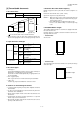
UX-108U/178U/188U FO-375U [3] Transmittable documents 5. Automatic Document Feeder Capacity 1. Document Sizes Number of pages that can be placed into the feeder at anytime is as follows: Normal size width 5.8" – 8.5"(148 – 216 mm) Normal size: max. ADF 20 sheets (14 lbs – 20 lbs) length 5.5" – 11"(140 – 279 mm) Special size: single sheet only (manual feed) NOTES: (Max.) (Min.) 140mm 148mm • 600mm (Max.
UX-108U/178U/188U FO-375U 7. Use of Document Carrier Sheet TELEPHONE JACK A document carrier sheet must be used for the following documents. • Those with tears. A standard RJ11C telephone jack must be located near the machine. This is the telephone jack commonly used in most homes and offices. • Those smaller than size 5.8"(W) x 5.5"(L) (148 mm (W) x 140 mm (L)). • Carbon-backed documents • Make print straight across paper E.G.
UX-108U/178U/188U FO-375U 3 Unwrap the roll of fax paper and place it in the compartment. 3. Original document support 1 Rotate the original document support so that it points straight out. • Important: The roll must be placed so that the leading edge of the paper unrolls as shown. (The paper is only coated on one side for printing. If the roll is placed backwards, the paper will come out blank after printing.) NO! YES 4.
UX-108U/178U/188U FO-375U 2 Remove the paper roll. 4. Clearing a jammed document If the original document doesn’t feed properly during transmission or copying, or DOCUMENT JAMMED appears in the display, first try pressing the START key. If the document doesn’t feed out, open the operation panel and remove it. Important: Do not try to remove a document without opening the operation panel. This may damage the feeder mechanism.
UX-108U/178U/188U FO-375U SETTING THE DATE AND TIME [5] Quick reference guide Press: 1 INSTALLATION FUNCTION 3 Display: DATE & TIME SET 2 START Press the START key: Enter two digits for the Month (01 through 12). Enter two digits for the Day (01 through 31). TEL SET. TEL LIN . E Enter four digits for the Year (EX: 1998). Enter two digits for the Hour (01 through 12). 3 Enter two digits for the Minute (00 through 59). Press the " " key for A.M. or the "#" key for P.M. When finished, press: 1.
UX-108U/178U/188U FO-375U (1) FU100 (ICP-S07) is installed in order to protect IC’s from an overcurrent generated in the motor drive circuit. If FU100 is open, replace it with a new one. CHAPTER 2. ADJUSTMENTS [1] Adjustments 3. Settings General (1) Dial mode selector Since the following adjustments and settings are provided for this model, make adjustments and/or setup as necessary. DIAL mode (Soft Switch No. SWB4 DATA No. 3) (step 1) Select "OPTION SETTING". 1.
UX-108U/178U/188U FO-375U [2] Diagnostics and service soft switch 1. Operating procedure (1) Entering the diagnostic mode Press FUNC → 9 → → 8 → # → 7 , and the following display will appear. ROM Ver. FWR0 (FWS0 ) After 2 sec: DIAG MODE FWR0 (UX-108U) FWS0 (UX-178U/188U/FO-375U) Then press the START key. Select the desired item with the key or the # key or select with the rapid key. Enter the mode with the START key.
UX-108U/178U/188U FO-375U 3. Diagnostic items description 3. 1. Soft switch mode 3. 6. Signal send mode The mode is used to send various signals to the circuit during FAX communication. Every push of START key sends a signal in the following sequence. Moreover, the signal sound is also output to the speaker when the line monitor of the soft switch is on. Used to change the soft switch settings. The soft switch which is stored internally is set by using the keys.
UX-108U/178U/188U FO-375U 3. 12. Entry data receive 3. 13. Cutter aging (Cutter model only) In this mode, the registered data sent from the other machine are received and the received data are registered in the own machine. When this mode is used for receiving, the other machine must be in the entry data send mode. The mode is used to continuously cut the recording paper to approx. 10 mm and display the number of cutting times.
UX-108U/178U/188U FO-375U 5. Soft switch description • Soft switch SW NO. SW l A1 DATA NO.
UX-108U/178U/188U FO-375U SW NO. SW l A6 DATA NO.
UX-108U/178U/188U FO-375U SW NO. DATA NO. 1 Switch setting and function ITEM 1 DTMF signal transmission level (High) 2 SW l B6 No. = Binary input 0 16 8 4 2 1 0 3 4 1 2 3 4 5 0 0 1 1 1 (0.5 x 7 = -3.5 dBm) 1 6 Reserved 0 7 8 Reserved Reserved 0 0 Factory Light Dark setting No. 1 0 1 0 1 0 2 No. 2 0 Factory 0 Light 1 Dark 1 Darker in 0 setting 3 4 0 1 0 1 0 No.
UX-108U/178U/188U FO-375U SW NO. SW l E2 DATA NO. Switch setting and function ITEM 1 1 Reserved 0 2 3 Reserved Reserved 0 0 4 5 Reserved Reserved 0 0 6 Reserved 0 7 Reserved 0 8 Reserved 1 2 3 Protection of remote reception (5 4 Remote reception with GE telephone 5 6 Remote operation code figures by external TEL (0~9) 50ms 80ms 100ms 120ms No. 1 0 0 1 1 0 No. 2 0 1 0 1 0 ) detect Yes Compatible No.
UX-108U/178U/188U FO-375U SW NO. SW l H1 DATA NO.
UX-108U/178U/188U FO-375U SW NO. SW l I5 SW l I6 SW l I7 SW l J1 DATA NO.
UX-108U/178U/188U FO-375U SW NO. DATA NO.
UX-108U/178U/188U FO-375U • Soft switch function description SW-A2 No. 7 Communication error treatment in RTN sending mode (Reception) SW-A1 No. 1 Protect from echo Used to determine communication error treatment when RTN is sent by occurrence of a received image error in G3 reception. When it is set to "1", communication error is judged as no error. Used to protect from echo in reception. SW-A1 No. 2 Forced 4800BPS reception SW-A2 No.
UX-108U/178U/188U FO-375U SW-A5 No. 8 Anti junk fax check SW-B4 No. 1 Auto dial mode Delay timer of before line connect When use the Anti junk fax function, set to "1". Delay time between the dial key input and line connection under the auto dial mode. SW-A6 No. 1 Auto gain control (MODEM) RAPID01 When this mode is enabled, if the reception signal level is under 31dBm. The modem itself controls the signal gain automatically. CML RELAY ON DIALLING SW-A6 No.
UX-108U/178U/188U FO-375U SW-C1 No. 7 MTF correction in half tone mode SW-D2 No. 4 Reserved This allows selection of MTF correction (dimness correction) in the half tone mode. When "NO" (=1) is selected, the whole image becomes soft and mild. On the contrary, however, clearness of characters will be reduced. Normally set to "YES" (=0). Set to "0". SW-D2 No. 5 Caller ID function Used for Caller ID function. SW-D2 No. 6, No. 7 CI off detection timer (Distinctive ring setting off only) SW-C1 No.
UX-108U/178U/188U FO-375U SW-G1 No. 1 ~ No. 4 Quiet detect time SW-H2 No. 4 ~ No. 8 Reserved When an answering machine is connected, if a no sound state is detected for a certain period of time, the machine judges it as a transmission from a facsimile machine and automatically switches to the FAX mode. Set to "0". SW-G1 No. 5 ~ No. 8 Quiet detect start timing SW-I2 No. 1 ~ No. 8 Reserved Inserts a pause before commencing quiet detection. Set to "0". SW-G2 No. 1 ~ No. 8 Reserved SW-I3 No. 1 ~ No.
UX-108U/178U/188U FO-375U SW-J3 No. 5 ~ No. 8 Reserved Set to "0". SW-K1 No. 1 Entering DIAG mode by pressing SPEED key A bit which is used in the production process only. When the SPEED key is pressed, the switch is changed from the stand-by state to the DIAG mode. SW-K1 No. 2 ~ No. 8 Reserved Set to "0". SW-L1 No. 1 ~ No. 8 Reserved Set to "0". SW-L2 No. 1 ~ No. 8 Reserved Set to "0".
UX-108U/178U/188U FO-375U [3] Troubleshooting Refer to the following actions to troubleshoot any of problems mentioned in 1-4. [1] A communication error occurs. [2] Image distortion produced. [3] Unable to do overseas communication. [4] Communication speed slow due to FALLBACK. • Increase the transmission level SOFT SWITCH A4-1, 2, 3, 4, 5. May be used in case [1] [2] [3]. • Decrease the transmission level SOFT SWITCH A4-1, 2, 3, 4, 5. May be used in case [3].
UX-108U/178U/188U FO-375U [4] Error code table 1. Communication error code table G3 Transmission Code Final received signal Error Condition (Receiver side) 0 Incomplete signal frame Cannot recognize bit stream after flag 1 NSF, DIS Cannot recognize DCS signal by echo etc.
UX-108U/178U/188U FO-375U 3-2. Automatic document feed CHAPTER 3. MECHANISM BLOCKS 1) Use of the paper feed roller and separation rubber plate ensures error-free transport and separation of documents. The plate spring presses the document to the paper feed roller to assure smooth feeding of the document. [1] General description 2) Document separation method: Separation rubber plate 1.
UX-108U/178U/188U FO-375U 3-5. Documents requiring use of document carrier 5. Recording block 1) Documents smaller than B6 (128mm x 182mm). 5-1. General view 2) Documents thinner than the thickness of 0.06mm. RECORDING BLOCK (NON CUTTER MODEL) 3) Documents containing creases, folds, or curls, especially those whose surface is curled (maximum allowable curl is 5mm). Scanner frame Thermal head 4) Documents containing tears. Paper guide upper 5) Carbon-backed documents.
UX-108U/178U/188U FO-375U [2] Disassembly and assembly procedures • • This chapter mainly describes the disassembly procedures. For the assembly procedures, reverse the disassembly procedures. • • The numbers in the illustration, the parts list and the flowchart in a same section are common to each other. Easy and simple disassembly/assembly procedures of some parts and units are omitted. For disassembly and assembly of such parts and units, refer to the Parts List.
UX-108U/178U/188U FO-375U 2 Parts list (Fig. 2) PWB case top, bottom and PWB No. Q’ty No.
UX-108U/178U/188U FO-375U 3 Parts list (Fig. 3) Operation panel unit and scanner frame No. 1 16 Q’ty No.
UX-108U/178U/188U FO-375U 4 Parts list (Fig. 4) Document guide upper unit and head frame No. Q’ty No.
UX-108U/178U/188U FO-375U 5 Parts list (Fig. 5) Document guide upper No. Q’ty No.
UX-108U/178U/188U FO-375U 6 Parts list (Fig. 6) Operation panel No. 1 6 2 12 7 3 13 8 4 14 9 5 15 Q’ty No.
UX-108U/178U/188U FO-375U 7 Parts list (Fig. 7) Drive unit, PWB and cutter No. Q’ty No.
UX-108U/178U/188U FO-375U Parts list (Fig. 8) Speaker, paper sensor lever and paper guide upper 8 No. Part name Q’ty 1 Mechanism unit 1 2 Paper sensor lever spring 1 (Cutter model only) 3 Paper sensor lever (Cutter model only) 4 Screw 2 5 Speaker 1 6 Paper guide upper (Non cutter model only) 1 1 5 2 4 3 5 6 Hook Rib 1 Hook 1 6 3 4 4 2 5 1 6 2 1 3 Fig.
UX-108U/178U/188U FO-375U 9 Parts list (Fig. 9) Drive frame (Non cutter model) No. 1 Q’ty No.
UX-108U/178U/188U FO-375U 10 Drive frame (Cutter model) Parts list (Fig. 10) No. Q’ty No. Q’ty No.
UX-108U/178U/188U FO-375U 11 Parts list (Fig. 11) Wire treatment No.
4–1 EXT.
FG 4–2 14 OPERATION PANEL PWB CNLCD LCD UNIT CNPN CONTACT IMAGE SENSOR THERMAL HEAD [2] Wiring diagram 15 7 16 CNCIS CNTH TX/RX MOTOR CNPN CNMT 6 CNCUT1 2 CUTTER SENSOR SPEAKER 2 CNSP CNPW CNLIUA UX-178U/188U/FO-375U ONLY CONTROL PWB UNIT CNCSW 2 CAM SW 10 12 FG POWER SUPPLY PWB UNIT CN2 CNLIU TEL/LIU PWB UNIT MJ1/2 MJTEL TEL LINE EXTERNAL LINE HANDSET AC CORD UX-108U/178U/188U FO-375U
[3] Point- to-point diagram 4–3 CIS OPERATION PANEL PWB CNCIS 1 VO 2 DG 3 +5V 4 øT 5 CISCLK 6 GLED 7 +24V VO DG +5V øT CISCLK GLED +24V 1 2 3 4 5 6 7 CNPN 1 KEN4A 2 KEN3A 3 KEN2A 4 KEN1A 5 DG 6 DG 7 +5V 8 ORGSNS 9 FRSNS 10 E 11 SEN4 12 SEN3 13 SEN2 14 SEN1 15 SEN0 THERMAL HEAD CNPN 1 KEN4A 2 KEN3A 3 KEN2A 4 KEN1A 5 DG 6 DG 7 +5V ORGSNS 8 9 FRSNS 10 E 11 SEN4 12 SEN3 13 SEN2 14 SEN1 15 SEN0 CNTH 1 VTH 2 VTH 3 STRB1 4 STRB2 5 THI 6 RANK 7 MG 8 MG 9 MG 10 +5V 11 STRB3 12 STRB4 13 LATCH 14 PCLK 15 DATA
UX-108U/178U/188U FO-375U 3. Operational description CHAPTER 5. CIRCUIT DESCRIPTION Operational descriptions are given below: • [1] Circuit description When a document is loaded in standby mode, the state of the document sensor is sensed via the 1 chip fax engine (XFC3). If the sensor signal was on, the motor is started to bring the document into the standby position. With depression of the START key in the off-hook state, transmission takes place.
UX-108U/178U/188U FO-375U 3) 27C1000 (IC8): pin-32 DIP (ROM) [2] Circuit description of control PWB EPROM of 1Mbit equipped with software for the main CPU. 1. General description 3) W24257S-70LL (IC5): pin-28 SOP (RAM) Fig. 2 shows the functional blocks of the control PWB, which is composed of 4 blocks. Line memory for the main CPU system RAM area and coding/decoding process. Used as the transmission buffer. MAIN CONTROL BLOCK Memory of recorded data such as daily report and auto dials.
UX-108U/178U/188U FO-375U XFC3 (IC3) Terminal descriptions Pin Name Input Output Pin Description Type Type (Note: Active low signals have an "n" pin name ending.) Pin No. I/O 135 133 130 I I O HU H − O TU I/O TU 123XT RDn WRn ROMCSn CS1n CS0n MCSn SYNC REGDMA WAITn RASn CAS[1:0]n DWRn [1:6][8:13] [15:20][22:27] [136:139] [141:144] 128 127 120 122 57 121 126 124 125 113 [111:112] 109 CPU Control Interface − Modem interrupt, active low. (Hysteresis In, Internal Pullup.) − System clock.
UX-108U/178U/188U FO-375U XFC3 (IC3) Terminal descriptions Pin Name Pin No.
UX-108U/178U/188U FO-375U (2) Panel control block The following controls are performed by the XFC3.
UX-108U/178U/188U FO-375U (4) Modem (R96DFXL-CID) block FEATURES INTRODUCTION • Group 3 facsimile transmission/reception – ITU-TS V.29, V.27 ter, T.30, V.21 Channel 2, T.4 The Rockwell R96DFXL-CID MONOFAX modem is a synchronous 9600 bits per second (bps) half-duplex modem with error detection and DTMF reception. It has low power consumption and requires only a single +5V DC power supply. The modem is housed in a single VLSI device package.
UX-108U/178U/188U FO-375U R96DFXL-CID (IC2) Hardware Interface Signals Pin Signals – 100-Pin PQFP Pin No.
UX-108U/178U/188U FO-375U [3] Circuit description of TEL/LIU PWB (1) TEL/LIU block operational description 1) Block diagram TEL/LIU PWB CONTROL PWB CML TX CONT CML TEL LINE HS DETECTOR GAIN-C TX OUT H L SIGTX 1 MODEM (R96DFXL-CID) 0 RX IN EXT. 0 SIGRX RC VOL1 VOL B VOL A 1 CI DETECTOR RC VOL2 HANDSET TEL IN TEL OUT VOL A VOL B H SPEAKER SP AMP 0 SP OUT BZOUT 1 L XFC3 L BZ CONT SP MUTE TEL MUTE CI HS H RC VOL2 RC VOL1 GAIN-C TXCONT CML Fig.
UX-108U/178U/188U FO-375U 5. Externally connected TEL OFF HOOK detection circuit section • 7. Signal selection The following signals are used to control the transmission line of TEL/ FAX signal. For details, refer to the signal selector matrix table. The circuit current detection is turned on together with OFF HOOK of main body or OFF HOOK of externally connected TEL. ON of CML OFF is judged as OFF HOOK of externally connected TEL. [Control signals from output port] 6.
UX-108U/178U/188U FO-375U [Signals for status recognition according to input signals] NO Signal Name (CNLIU) NO Signal Name (CNLIU) 1 TELOUT 7 RXIN L: The handset is in the off-hook state. 2 3 TELIN TELMUTE 8 9 TXOUT CML Incoming call (CI) detection signal 4 CI 10 +24VA H: The handset or external telephone is in the 5 HS 11 +5V 6 RHS 12 DG Signal Name Function H: The handset is in the on-hook state. RHS CI on-hook state.
UX-108U/178U/188U FO-375U [4] Circuit description of power supply PWB 1. Block diagram F1 1.25A/250V AC IN Noise Filter Circuit Rectifying Smoothing Circuit Switching Circuit (RCC system) Regulater Circuit +5V +24V F3 4A/72V Photo Coupler Fig. 7 The overcurrent protection is performed by bringing Q1 to OFF state through detection of voltage increase in the auxiliary winding of T1 by ZD2 and R9. 2-1.
6–1 C160 C161 C162 C163 C164 C165 C166 D 52 51 50 49 55 54 47 46 44 43 42 40 39 38 C VSS GPO0 GPO1 GPO2 GPO3 VDRAM 106 SM0 105 SM1 104 SM2 103 SM3 VSS C167 1000P C168 1000P C169 1000P C170 1000P 118 117 116 RA2 115 470x4 114 RA6 470x4 L104 Z2145 R172 470 RA7 470 x 4 KEN1A KEN2A KEN3A KEN4A R239 120 E SEN0 SEN1 SEN2 SEN3 SEN4 DG VREFCONT BZCONT GAINC TXCONT DG DG DG DG DG DG DG F DG C128 22P +VREF –VREF VIN THADI BZOUT C171 1000P TPA TPB TPA RA3 TPB 470 x 4 DG DG DG DG E 59 71 66 67 65
6–2 1 2 3 4 5 6 A (1-3I) (1-3I) (1-6I) (1-5I) RD ROMCS D[7~0] A[16~0] Memory block A A16 A15 A14 A13 A12 A11 A10 A9 A8 A7 A6 A5 A4 A3 A2 A1 A0 B B 2 3 29 28 4 25 23 26 27 5 6 7 8 9 10 11 12 22 24 A16 A15 A14 A13 A12 A11 A10 A9 A8 A7 A6 A5 A4 A3 A2 A1 A0 E G 21 20 19 18 17 15 14 13 GND 16 31 (A17) 32 VCC 1 VPP DQ8 DQ7 DQ6 DQ5 DQ4 DQ3 DQ2 DQ1 IC8 27C010 +5V C140 0.1 C DG C (1-3I) (1-3I) (4-1D) D7 D6 D5 D4 D3 D2 D1 D0 D CE1 WR CE2 VBT D R146 22K R120 N.M.
6–3 A MDMRST SYSCLK MCS RD WR MIRQ C 63 100 1 2 3 4 5 R162 R157 R158 R159 470 470 470 470 R132 N.M. MPXC VOLB VOLA RCVOL2 RCVOL1 MPXA R160 N.M. DG BYPASS D R166 10K R135 E C107 18P 90 86 84 74 26 83 25 85 36 N.M. 40 TXLOSS1 39 TXLOSS2 38 TXLOSS3 MAG R110 120 DG ADOUT ADIN RCVO RCVI RXIN AOUT RAMPIN AGD N.C. N.C. N.C. +5VA 0VA 0VA 0VA 0VA 0VA DG C106 15P R111 200 N.C. N.C. N.C. N.C. N.C. N.C. N.C. N.C. TXOUT DAOUT DAIN SWGAIN0 SWGAIN1 X1 24.
6–4 A +5V CNCUT1-1 (*1) CNCSW-1 CNPN-9 DG CNPN-8 R215 30K CUT1 CSW DG 2 1 5 GND 3 SUB MRST VCC (*1) DG 4 8 4 B R121 R101 1K PSNS R196 R206 470 R171 Z2139 (*1) IC10 2904 DG C152 0.1 R145 470 1 IC100 PST596CNR 4 3 DG DG 2 1 C151 0.1 C133 0.1 C124 0.1 C139 DG DG DG 2 – 3 + R212 5.6K R207 3.3K DG DG R214 270 PI1 R100 C100 1 +5V FRSNS SW1 DOOR SW ORGSNS +5V B OUT 1 2 3 4 5 6 Other block A C DG E R117 B C N.M.
1 2 3 4 5 C A (1-1E) CNCIS-1 (5-5H) DG E B LEDON B C DG R217 R232 30K R218 10K +24V DG R188 5 6 +5V C R210 7 C141 1000P IC10 2904 IC9 2902 1 Q101 2SC2412 R189 1.5K DG 2 – 3 + R209 +5V Q102 2SA1036 +5V DG R190 5.
6–6 1 2 3 4 5 6 B A (3-1C) (3-1C) (3-3H) (3-3H) (1-1E) (3-3H) (1-1E) R213 33K R211 33K DG +5V RCVOL2 RCVOL1 AGD SIGRX GAINC SIGTX TXCONT C153 1 R216 3K 3 VREF R165 30K R164 2K 1 B 5 IC4 4066 IC4 4066 +5V R221 0 +5V D100 1SS355 C146 1 Analog signal block A R192 86.6K 4 2 R220 10K R223 47K 13 IC9 2902 7 DG DG C154 0.1 14 C148 0.1 11 4 DG IC9 2902 R222 47K C 14 C6 10/50 C155 1000P 13 – 12 + 8 IC9 2902 R195 86.
UX-108U/178U/188U FO-375U Control PWB parts layout (Top side) 6–7
UX-108U/178U/188U FO-375U Control PWB parts layout (Bottom side) 6–8
6–9 1 2 3 4 5 6 B A MJ2-4 MJ2-3 MJ1-4 MJ1-3 3 4 3 4 ARG VA2 C9 1000P C10 1000P B L2 L5 L4 HS CI N.M. N.M. L3 ERZV5D471x2 VA1 HOOK SW PC1 PC814 PC2 TLP521-1 EXT-R EXT-T RING AR1 RA391PV62 TIP [2] TEL/LIU PWB circuit A RHS CNLIU-6 CNLIU-5 CNLIU-4 N.M. N.M. C R3 30 R4 91 ZD2 HZ2C1 C PC1 PC814X ZD1 HZ2C1 CNLIU-11 CNLIU-12 CNLIU-10 CNLIU-9 D CML C D CML B R23 1K E R6 22K C6 22/50 DG D3 1SS270 CML E N.M.
UX-108U/178U/188U FO-375U TEL/LIU PWB parts layout 6 – 10
6 – 11 1 2 A F1 1.25A/250V 3 AC N 1 D2 AC L CN1 D1 R1 560K C1 0.1 V1 240V L1 D4 B C13 3300P C5 220/200 R4 100 C9 0.068 C Q1 FS10KM C7 1000P Q2 2SC2655-Y Q4 2SC1741AS R3 8.2k R2 0.18 C C8 0.01 3 4 C14 1000P D R8 680 D6 IS2076A C6 0.01 C12 4700P R11 R9 680 680 PC1 PS2501-1 R10 22 D5 ERA22-06 R6 150K R6 680 R7 82K R5 180K D ZD2 RD3.9ESAB2 N.M. V2 C3 C4 D3 RL1N4004 x 4 TH1 8.
UX-108U/178U/188U FO-375U Power supply PWB parts layout 6 – 12
6 – 13 C1 0.022 11 12 13 1 2 3 4 5 10 R8 1K R1 6.2K VO A SG266 ORGSNS K R7 220 C E FRSNS DELETE PLAY REPEAT R9 100K R2 100K R11 100K R12 100K R6 100K A B C D ORGSNS E FRSNS CNPN-9 CNPN-8 REC # 0 START 9 8 3 COPY 2 6 02 CNLCD-6 CNLCD-5 CNLCD-3 CNLCD-2 CNLCD-1 E 5 STOP REMINDER 01 +5V UP DOWN RECEPTION RESOLUTION D FUNC R10 100K Note: Since the parts of this PWB can not be supplied, change it as a unit. C2 22/50 8 GND VCC A0 D1 A1 D2 A2 D3 A3 D4 D5 N.C.
UX-108U/178U/188U FO-375U CHAPTER 7.
UX-108U/178U/188U FO-375U [2] Power on sequence START CPU initialized MODEM initialized “WAIT A MOMENT” display STOP key ? NO “MEMORY CLEAR ?” display NO 3 sec ? YES 1 YES STAND-BY START key ? NO 2 YES COPY key ? 1 2 “MEMORY CLEARED” display “MEMORY CLEARED” display Memory clear Memory clear STAND-BY PROCESS CHECK MODE NO YES STOP key ? NO 3 sec ? NO YES STAND-BY 7–2
UX-108U/178U/188U FO-375U CHAPTER 8. OTHERS [1] Service tools 1. List NO. PARTS CODE 1 2 CPWBS2915SCS1 PSHEZ3354SCZZ DESCRIPTION PRICE RANK BN AD Q’TY Relay board unit Shading wave memory standard paper 1 1 Relay board unit +5V (TP2) DG (TP1) R100 PSNS (TP3) NO.
UX-108U/178U/188U FO-375U 2. Description 2-1. Relay board unit 1. Remove the TEL/LIU PWB, control PWB and Power Supply PWB from this unit, and mount the relay board unit instead. • Before connecting the wiring to the relay board unit, set the test PWB switches to the fixed position. 2. The setting is as follows. • The relay cables are used as one pair. • The sensor is wired as shown in the following figure. • The door swich and hook switch are manually operated.
UX-108U/178U/188U FO-375U 3. Shading paper The white and black basis is applied to remember the shading waveform. Be sure to perform this operation when replacing the battery or replacing the control PWB. Execute in the shading mode of DIAG mode.
UX-108U/178U/188U FO-375U [2] IC signal name CONTROL PWB UNIT IC10: VHiNJM2904M-2 (NJM2904M) IC5: VHiW24257S7LL (W24257S-70LLT) (TOP VIEW) (TOP VIEW) 8 1 + – 2 A 7 3 4 + B – 6 PIN NAME 1. A OUTPUT 2 .A–INPUT 3. A+INPUT 4. GND 5. B+INPUT 6. B–INPUT 7. B OUTPUT 8.
UX-108U/178U/188U FO-375U IC9: VHiLM2902D/-1 (LM2902D) A OUTPUT 1 A-INPUT 2 A+INPUT 3 V+ B+INPUT IC8: VHi27C1000PC5 (27C010) EP-ROM 14 D OUTPUT A – + D 13 D-INPUT + – 11 GND 10 C+INPUT 5 6 B OUTPUT 7 32 VCC A16 2 31 PGM A15 30 NC 3 12 D+INPUT 4 B-INPUT (TOP VIEW) 1 VPP – + B + – C 9 C-INPUT 8 C OUTPUT A12 4 29 A14 A7 5 28 A13 A6 6 27 A8 A5 7 26 A9 A4 8 25 A11 A3 9 24 G A2 10 23 A10 A1 11 22 E A0 12 21 DQ8 DQ1 13 20 DQ7 DQ2 14 19 DQ6 DQ3 15 1
UX-108U/178U/188U FO-375U 81 0VD2 82 DCLK 83 EYESYNC 84 EYECLKX 85 EYECLK 86 EYEX 87 ADIN 88 DAOUT 89 0VD2 90 EYEY 91 GP21 92 0VD2 93 GP20 94 GP19 95 RXD 96 RLSDn 97 0VD2 98 RCVO 99 SWGAINO 100 GP02 IC2: VHiR96XFC3CID (96DFXL-CID) 74 SYNCIN2(G2XCLK) D7 8 73 DCLKI(IRQ2n) D6 9 72 +5VD1 D5 10 71 YCLK D4 11 70 XCLK D3 12 69 XTLO D2 13 68 XTLI D1 14 67 PORin D0 15 66 0VD2 0VD2 16 65 EN85n 0VA 17 64 RTSn RAMPIN 18 63 GP11 NC 19 62 SEE NOTE 1 NC 20 61 G
UX-108U/178U/188U FO-375U IC3: VHiR96XFC3CID (XFC3) PM1/GPO1 PM2/GPO2 PM3/GPO3 VDRAM RASN CAS0N CAS1N WRPROTN DWRN 117 116 115 114 113 112 111 110 109 118 120 119 121 TONE ROMCSN 122 PM0/GPO0 MCSN 123 124 VDDI 125 CSIN WAITN REGDMA 126 129 SYNC DEBUGN 130 128 TSTCLK 131 127 RESETN 132 RDN VSSO 134 133 WRN VSSI SYSCLK 135 139 MIRON 140 136 D4 141 D7 VDDO 142 138 D3 143 137 D2 144 D6 D1 D5 D0 A23 1 108 VSSO A22 2 107 GPIO20/ALTTON
UX-108U/178U/188U FO-375U PARTS GUIDE UX-108 UX-178 UX-188 MODEL FO-375 Non Cutter model Cutter model UX-108 UX-178/188 FO-375 CONTENTS 1 Cabinet, etc.
UX-108U/178U/188U FO-375U [1] Cabinet, etc.
UX-108U/178U/188U FO-375U NO. PARTS CODE PRICE RANK NEW MARK PART RANK AP AC AC AC AD AC AC AD AP AE BP BL BF BF AA AD AL AL AT AT AT AC AC BE AN AN AT BN AH AH AH AD AH AC AC AC AC AL AF AH AD AH AD AF AG AH BF BF AD AC AD BV BZ AC AC AC AC AD AX AK AT AE AF AC AD AH AD AC AF AF N N N N N N N N N N N N N N C C C C C C C C C C B E E E C C C C D D D C C E C C B E C C C C C C C C C C C C C C C C C C B B C C C E E C C C C C C C C C C C C C C C B B DESCRIPTION [1] Cabinet etc.
UX-108U/178U/188U FO-375U [2] Upper cabinet 11 1 7 6 9 8 B2 10 13 2 5 12 B3 3 B3 4 14 [3] Document guide upper 3 2 7 8 5 4 6 15 9 10 1 11 1 16 14 12 13 –3–
UX-108U/178U/188U FO-375U NO.
UX-108U/178U/188U FO-375U [4] Drive unit (Non cutter model) (UX-108) B4 16 19 12 1 18 2 5 13 8 13 11 4 8 3 11 6 13 12 9 [5] Drive unit (Cutter model) (UX-178/188/FO-375) B4 16 19 12 1 13 18 8 5 2 13 17 8 18 15 4 11 10 3 11 6 11 15 13 12 8 7 13 9 14 –5–
UX-108U/178U/188U FO-375U NO.
UX-108U/178U/188U FO-375U [6] Packing material & Accessories 4 8 3 10 15 1 2 TAPE 14 6 13 7 AC CORD 11 9 12 5 NO.
UX-108U/178U/188U FO-375U NO.
UX-108U/178U/188U FO-375U NO.
UX-108U/178U/188U FO-375U NO.
UX-108U/178U/188U FO-375U NO.
UX-108U/178U/188U FO-375U NO.
UX-108U/178U/188U FO-375U Index PARTS CODE [C] CCNW-4745XH01 [D] DCEKC586JXHZZ ″ DCEKC587JXHZZ ″ DCEKL366BXH01 ″ DCEKP367BXH01 DCEKP370BHX04 DCEKP370BXH01 ″ DCEKP370BXH04 DCEKP370BXH05 ″ DUNTK369BXHBE DUNTK369BXHOG DUNTK369BXHSG [G] GCABA2297XHZA GCABA2297XHZB GCABA2297XHZC GCABB2298XHZA GCABB2298XHZB GCABB2298XHZC GCASP2099XHZZ GCASP2100XHZZ GDAI-2078XHZA GDAI-2078XHZB GDAI-2078XHZC GLEGG2068XHZZ [H] HPNLH2383XHZA HPNLH2383XHZB HPNLH2383XHZC HPNLH2383XHZD [J] JBTN-2216XHZA JBTN-2216XHZB JBTN-2216XHZC JBTN
UX-108U/178U/188U FO-375U PARTS CODE VCCCTV1HH220J ″ ″ ″ ″ ″ ″ VCCSTV1HL102J VCCSTV1HL391J VCEAGA1EW476M ″ ″ VCEAGA1HW105M VCEAGA1HW106M ″ ″ VCEAGA1HW107M VCEAGA1HW225M VCEAGA1HW226M ″ VCEAGA1HW475M ″ ″ ″ ″ VCKYPU1HB102K ″ ″ ″ VCKYPU1HB103K VCKYPU1HB221K VCKYPU1HB222K ″ ″ VCKYPU1HB332K VCKYPU1HF223Z VCKYTQ1HF104Z ″ VCKYTV1CF105Z ″ ″ ″ ″ ″ ″ ″ ″ ″ ″ ″ ″ ″ ″ ″ ″ ″ ″ ″ VCKYTV1EB104K ″ ″ ″ ″ ″ ″ ″ ″ VCKYTV1EF104Z ″ ″ ″ ″ ″ ″ ″ ″ ″ ″ VCKYTV1HB102K ″ No.
UX-108U/178U/188U FO-375U PRICE NEW PART RANK MARK RANK PARTS CODE No.