UX-2200CMU/CMC FO-2150CMU/CMC TECHNICAL MANUAL No. 00ZU220CMUTME FACSIMILE INK JET PRINTER MODEL UX-2200CM FO-2150CM This Technical Manual contains detailed information about the printer for the UX- 2200CM / FO-2150CM to the Service Manual already issued. CONTENTS [1] Engine Specifications ........................................................................................................................... 1 [2] Abbreviations ........................................................................
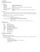
UX-2200CMU/CMC FO-2150CMU/CMC [1] Engine Specifications 1. Mechanism Resolution Print Speed Print Swath Duty Cycle Dimensions (approximate) Weight (approximate) Acoustics : 600 dpi x 600 dpi addressability : 3 PPM draft text with black cartridge : 8 inches : Up to 500 pages per month maximum, 170 pages per month average : 350mm x 125mm x 60mm : 1.2 pounds : 45 dBA in letter quality mode (using Lexmark paper feed and covers which is not included) 2.
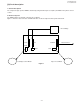
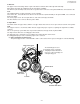
UX-2200CMU/CMC FO-2150CMU/CMC [4] Circuit description 1. General description The compact design of printer PWB is obtained by using 8 bit microprocessor(CPU) and ASIC in the printer control section. 2. Electrical System The PWB provides mechanical control for Ink Jet Printer. Figure 1 shows the interconnection of PWB and other electrical component in the print mechanism.
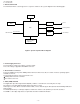
UX-2200CMU/CMC FO-2150CMU/CMC 3. Electricai Overview The information in this section appears in a sequence relative to the system diagram in the following figure. SRAM 8bit MPU ASIC TO FAX PWB Host Interface Driver Head Driver Carriage Motor Driver Feed Motor Sensor •Home Position •Paper-IN Figure 2 System of printer Block diagram 4. Power Supply Connector The mechanism requires two voltages (+5V and +24V). These two voltages supplied from CNPRT connector. 5.
UX-2200CMU/CMC FO-2150CMU/CMC 7. Driver IC The paper motor and carriage motor require current that cannot be driven directly from ASIC chip. Motor driver IC provide the additional current and voltage capability. The driver IC (IC1 and IC2) located near the respective motor connector on the printer PWB also connect back to the ASIC. Two additional drivers IC drive 56 nozzles on the cartridge.
UX-2200CMU/CMC FO-2150CMU/CMC (2) Print transfer The planetary gear turns clockwise and is disconnected from the PU gear,so that the paper is not fed automati cally. In case of hand paper feed the paper is fed directly to the transfer roller. HAND FEED PAPER PLANET GEAR MOTOR GEAR AUTOMATIC FEED PAPER PU GEAR When the mechanism stops, the automatic paper feed is not performed PRINTER FEED GEAR 9.
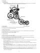
UX-2200CMU/CMC FO-2150CMU/CMC 12. Home Position Sensor LEFT RIGHT B C A CARRIAGE HOLDER The home position of carriage is detected as a result of change of output of photointurrupter A which is caused due to shutting-off of optical path of photointerrupter A by the slit B . While the photointerrupter is shut off by the slit B, the output (pin 1 of CN3) of photointerrupter gets H level (+5V). If it is not shut off, the output gets L level (0V). In the home position the output is L.
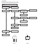
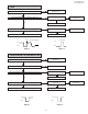
UX-2200CMU/CMC FO-2150CMU/CMC [5] Overall Trouble Shooting Of Printer PWB • BOTH CARRIAGE MOTOR AND FEED MOTOR ARE NG. REPLACE F100 AND F101 FUSE “F100” AND “F101 OPEN OK +24V AT Q1-E (Figure 1) +24V AT Q1-C (Figure 1) NG NG CHECK RESISTANCE BETWEEN +24V AND GND.
UX-2200CMU/CMC FO-2150CMU/CMC • FEED MOTOR IS NG (CARRIAGE MOTOR IS GOOD) FUSE “F101” OPEN Check theREPLACE laser diode driver. F101 OK CHECK WAVEFORMS IC2 ( 2,4,6,8 pin) (Figure 4) CHECK IC5 NG NG REPLACE IC5 OK OK REPLACE PRINTER PWB CHECK WAVEFORMS IC2 ( 3,5,7,9 pin) (Figure 3) CHECK IC2 NG REPLACE IC2 NG OK OK REPLACE PRINTER PWB REPLACE PRINTER PWB +40~50V IC2-2,4,6,8PIN INCLUDE OVERSHOOT 1.5V +24V GND GND Figure 4 Figure 3 • CARRIAGE MOTOR IS NG (FEED MOTOR IS OK).
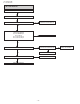
UX-2200CMU/CMC FO-2150CMU/CMC • MISSING NOZZLES (RESULT OF CHECK PATTERN OR CLEAN NOZZLES CLEAN NOZZLES NG REPLACE ANOTHER CARTRIDGE NG MISSING MANY NOZZLES CHECK IC AND CONNECTOR BY REFERING TO THE TABLE 1&2 NO YES CHECK THE SOLDER IC4, IC6 COMMON pin IC 5 82-89 pin IC4 1,4,40,41,43,44 pin IC6 1,4,40,41,43,44 pin CORRECT SOLDER NG OK CHECK +24V AT R1,R2,R6, AND R7 CHECK RESISTANCE BETWEEN +24V AND GND.
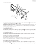
UX-2200CMU/CMC FO-2150CMU/CMC [6]How to Decide the Number of the Wrong Nozzle FUNC + 6 + + “CLEAN NOZZLES” A B Nozzle 1 Nozzle 56 Horizontal lines on A and B correspond to nozzle #1,#2....#56 from left side to right side. If there are missing horizontal lines, you can decide the number of wrong nozzle from pattern A or B . Note) Don’t use the check pattern to decide the number of wrong nozzle.
UX-2200CMU/CMC FO-2150CMU/CMC TABLE 1. TABLE 2.
UX-2200CMU/CMC FO-2150CMU/CMC [7] Waveforms FEED MOTOR WAVEFORMS WHEN FEEDING PAPER Stopped CH1=50V DC P:10 T:1.92ms T CH2=50V DC P:10 1/ T:520.
UX-2200CMU/CMC FO-2150CMU/CMC CARRIAGE MOTOR WAVEFORMS Stopped CH1=20V DC P:10 T:19.2¨s T CH2=20V DC P:10 1/ T:52.08kHz CH3=20V DC P:10 CH4=20V DC P:10 20s / d CN2-1 1 CN2-2 2 CN2-3 3 CN2-4 4 When the cartridge holder is at the position of replacing cartridge. Figure 2 Stopped CH1=20V DC P:10 T:960¨s T CH2=20V DC P:10 1/ T:1.
UX-2200CMU/CMC FO-2150CMU/CMC CARRIAGE MOTOR WAVEFORMS MEASURED FOR CHECKING OUT OF INK Stopped CH1=20V DC P:10 T:1.92¨ms T CH2=20V DC P:10 1/ T:520.8Hz CH3=20V DC P:10 CH4=20V DC P:10 2ms / d CN2-1 1 CN2-2 2 CN2-3 3 CN2-4 4 Figure 4 Stopped CH1=20V DC P:10 T:480¨s T CH2=20V DC P:10 1/ T:2.
UX-2200CMU/CMC FO-2150CMU/CMC [8] Service Checks 1. Carrier Transport Service Check 1 FRU Action System Board Check the motor for binds,or loose motor pulley. Turn the printer off and disconnect CN2 from the system board.Check for motor pins shorted to the motor housing.If you find a pin shorted to the housing,replace the motor. If the failure remains,replace the system board.
UX-2200CMU/CMC FO-2150CMU/CMC 2. Envelope Feed Service Check 1 FRU Action Envelope Guide Be sure the envelope guide has been turned to the envelope load position. Be sure the envelope guide is against the envelopes. Perform the ‘Paper Feed Service Check’on page 4. 3. Maintenance Station Service Check The maintenance station has two functions: • • Cleans the printhead nozzles during the print operation. Seals the printhead when it is not being used to prevent the nozzles from drying.
UX-2200CMU/CMC FO-2150CMU/CMC 4. Paper Feed Service Check If your machine does not have paper jam problems, continue with the service check. If your machine does have a paper jam problem,examine it for the following before you begin the service check: • • • • Check the entire paper path for obstructions. Be sure there is not too much paper in the sheet feeder. Be sure the correct type of paper is being used. Check for static in the paper.
UX-2200CMU/CMC FO-2150CMU/CMC 5. Paper Path Service Check Examine the machine for the following before you being this service check: • • • Check the entire paper path for obstructions Be sure the correct type of paper is being used. Be sure the printer is installed on a flat surface. FRU Action 1 Large and Small Feed Rollers Check for wear and binds. 2 Small Feed Roller Springs Check for damage. 3 Auto Sheet Feeder Check the pick rollers for wear.
UX-2200CMU/CMC FO-2150CMU/CMC P14(PPG) P13(DVO) P12(INT2/TC1) P11(INT1) P10(INT0) P51 P50 P67 P66 P65 P64 [9] IC Signal Name IC 8 : VHiTMP87PH47U (TMP87C807U) 33 32 31 30 29 28 27 26 25 24 23 1. Pin Assignment (Top View) 22 21 20 19 18 17 16 15 14 13 12 34 35 36 37 38 39 40 41 42 43 44 P63 P62 P61 P60 N.C.
UX-2200CMU/CMC FO-2150CMU/CMC 3. Pin Function PIN Name P07 to P00 P17,P16 P15(TC2) P14(PPG) P13(OVO) P12(INT2/TC1) P11(INT1) P10(INT0) P22(XTOUT) P21(XTIN) P20(INT5/STOP) P51,P50 P67 to P60 Input/Output I/O I/O I/O(Input) I/O(Output) Output I/O(Output) 2-bit output port with latch. P77(HSO) P76(HSCK) P75(SO) P74(SI) P73(SCK) P72(PWM/PDO) P71(INT4) P70(INT3/TC3) XIN/XOUT I/O(Output) 8-bit programmable input/output port (tri- HSO serial data output state).
UX-2200CMU/CMC FO-2150CMU/CMC IC 4 , 6 : VHil6451///-1 (L6451) IN C IN B GND IN A COM 1 43 42 41 40 LOGIC SUPPLY 2 IN D GND 3 1 COM 2 4 44 OUT 27 CHIP ENABLE 6 5 1. Pin Connection (Top View) OUT 26 7 39 OUT 0 OUT 25 8 38 OUT 1 OUT 24 9 37 OUT 2 OUT 23 10 36 OUT 3 OUT 22 11 35 OUT 4 OUT 21 12 34 OUT 5 OUT 20 13 33 OUT 6 OUT 19 14 32 OUT 7 OUT 18 15 31 OUT 8 GND 16 30 OUT 9 N.C. 17 29 GND 20 21 22 23 24 25 26 27 N.C.
UX-2200CMU/CMC FO-2150CMU/CMC 3. Description The L6451 is realized in Multipower BCD Technology which combines isolated DMOS power transistors with CMOS and Bipolar circuits on the same IC. By using mixed technology it has been possible to optimize the logic circuitry and the power stage to achieve the best possible performances.
UX-2200CMU/CMC FO-2150CMU/CMC [10] Exploded View 8 Printer unit 59 B12 B12 35 57 34 41 47 51 B12 901 903 28 38 58 a 50 49 B12 52 W2 B3 52 B12 22 6 39 5 a 30 38 44 29 31 43 W2 27 7 38 W1 42 46 36 11 12 9 8 43 40 48 23 B12 B5 45 3 53 B1 902 13 901 2 901 11 56 1 16 54 17 19 20 21 24 18 10 36 B4 14 15 45 56 37 55 INK SENSOR PWB B14 B10 32 4 26 904 25 905 Note : Since the parts circled by dots can not be supplied, change it as a unit – 23 –
UX-2200CMU/CMC FO-2150CMU/CMC [11] Replacement Parts List NO.
UX-2200CMU/CMC FO-2150CMU/CMC COPYRIGHT © 1998 BY SHARP CORPORATION ALL RIGHTS RESERVED. No part of this publication may be reproduced, stored in a retrieval system, or transmitted in any form or by any means, electronic, mechanical, photocopying, recording, or otherwise, without prior written permission of the publisher. SHARP CORPORATION Communication Systems Group Quality & Reliability Control Center Higashihiroshima, Hiroshima 739-0192, Japan Printed in U.S.A.