
Service manual

UX-A255U
[3] Circuit description of TEL/LIU PWB
(1) TEL/LIU block operational description
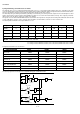
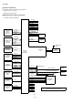
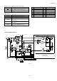
1) Block diagram
2) Circuit description
The TEL/LIU PWB is composed of the following 6 blocks.
1. Speech circuit section
2. Dial transmission section
3. Speaker amplifier section
4. Ringer circuit section
5. CI detection circuit
6. Signal/DTMF transmission level & receiving level
Fig. 5
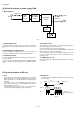
3) Block description
1. Speech circuit section
• The receiver volume is an electronic volume type, this model is
switched in 3 steps.
2. Dial transmission section
• D.P. transmission: The CML relay is turned on and off for control in
the DP calling system. (Refer to the attached sheet.)
• DTMF transmission: It is formed in the modem, and is output.
3. Speaker amplifier section
• Ringer volume :It is controlled by the combination of the
attenuator value of the LINE DRIVER in the
modem and the ringer sending level sent from
the modem.
• Speaker volume :It is controlled by the attenuator value of the
IC5 and IC3 (VOL-A,B,C)
4. Ringer circuit section
• The ringer sound is formed in the tone of modem when CI signal is
detected. The amplifier circuit drives the speaker of the main body.
5 – 10
DAC
LPF
DAC
H
L
CI DETECTOR
SPEAKER
LINE
+24VL
DG
CONTROL PWBTEL/LIU PWB
RX
TX
TEL MUTE
(H:MUTE)
PC1
Q101
IC7
IC102-A
Q102
IC101-B
Q105
Q104
IC101-A
IC102-B
IC5
0,1
0,0
1,0
1,1
RTLOOP
ADC
SIN
MIC
/LINE
SELECT
MODEM BLOCK
(20438 I/A)
SP OUT ENABLE
MIC ENABLE
LINE IN ENABLE
LINE OUT ENABLE
0,20,25,30dB
LINESEL
1,1
0,0
1,0
0,+4dB
SOUT
SPKRP
MICP
LINEIN
LINE
OUT
MUTE,0,-6,-12dB
IC3 SCE214V
FAX CONTROLLER
DTMFMUTE
BZOUT1
RCVOL
SP MUTE
TEL MUTE
CI
CML
MIC MUTE
VOL-A
VOL-B
VOL-C
SPOUT
SP MUTE
(H:MUTE)
TEL IN
RXIN
TXOUT
MIC MUTE
(H:MUTE)
CML
SIGTX
SIGRX
0,6dB
HANDSET