UX-B20U/UX-B20C/B25C SERVICE MANUAL No. 00ZUXB20U/SME FACSIMILE UX-B20 UX-B25 MODEL MODEL UX-B20 UX-B20/B25 Illustration: UX-B20U SELECTION CODE DESTINATION U U.S.A. C Canada CONTENTS CHAPTER 1. GENERAL DESCRIPTION [1] Specifications ................................................. 1-1 [2] Operation panel.............................................. 1-2 [3] Transmittable documents ............................... 1-3 [4] Installation ......................................................
UX-B20U/UX-B20C/B25C –i–
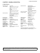
UX-B20U/UX-B20C/B25C UX-B20U/UX-B20C/B25C FAX Service E Market Manual 1. GENERAL DESCRIPTION CHAPTER [1] Specifications Automatic feeding: Width: 5.8 to 8.5" (148 to 216 mm) Length(10 sheets): 5.5 to 11" (140 to 279 mm) Length(5 sheets): 5.5 to 14" (140 to 356 mm) Manual feeding: Width: 5.8 to 8.5" (148 to 216 mm) Length: 5.5 to 23.6" (140 to 600 mm) 8.3" (210 mm) max. Effective scanning width: Horizontal: 203 pixels/inch (8 dots/ Scanning resolution: mm) Vertical:Standard: 98 lines/inch (3.
UX-B20U/UX-B20C/B25C [2] Operation panel 23 4 1 56 5 RESOLUTION/ RECEPTION INK 7 Z A 8 9 10 11 12 13 Illustration: UX-B20U 1. Display 8. POLL key This displays messages and prompts to help you operate the machine. 2. FLASH key This key is used for Call Waiting and other special service that requires subscription from your phone company. Your phone company will provide you with details on how to use the key. 3.
UX-B20U/UX-B20C/B25C [3] Transmittable documents 5. Automatic Document Feeder Capacity 1. Document Sizes Number of pages that can be placed into the feeder at anytime is as follows: Normal size Width Length Normal size: max. ADF 10 pages 148 - 216 mm 140 - 279 mm Special size: single sheet only (manual feed) NOTE: • When you need to send or copy more pages than the feeder limit, place additional pages in feeder when last page in feeder is being scanned.
UX-B20U/UX-B20C/B25C [4] Installation 2) Open the print compartment cover. 1. Site selection Take the following points into consideration when selecting a site for this model. ENVIRONMENT • The machine must be installed on a level surface. • Keep the machine away from air conditioners, heaters, direct sunlight, and dust. • Provide easy access to the front, back, and sides of the machine.
UX-B20U/UX-B20C/B25C 4. Attaching the paper tray 2) Insert the stack of paper into the tray, PRINT SIDE UP. 1) Attach the paper tray. • If paper remains in the tray, take it out and combine it into a single stack with the new paper. • Be sure to load the paper so that printing takes place on the print side of the paper. Printing on the reverse side may result in poor print quality. • GENTLY LOAD PAPER INTO THE PAPER TRAY. • DO NOT FORCE IT DOWN INTO THE FEED SLOT.
UX-B20U/UX-B20C/B25C 7. Installing the print cartridge 3) Open the print compartment cover. Follow these steps to install or replace the print cartridge. • When replacing the print cartridge, be sure to use a SHARP UXC70B cartridge. Print cartridge yield (at 4% coverage) Initial cartridge Quality mode OFF: Approx. 300 letter pages Quality mode ON: Approx. 200 letter pages Replacement cartridge (SHARP UX-C70B) Quality mode OFF: Approx. 600 letter pages Quality mode ON: Approx.
UX-B20U/UX-B20C/B25C 6) Insert the new print cartridge into the cartridge holder. 10)Press INK to make the print cartridge holder return to its home position. CHANGE CARTRIDGE 1=NEW, 2=OLD 11)Press (NEW) if the cartridge you installed is new. Press (OLD) if the cartridge you installed is old. 7) Place your index finger on the tab as shown and close the cartridge holder cover with your thumb. Make sure the cover clicks into place. Display when "NEW" is selected: NEW CART.
UX-B20U/UX-B20C/B25C 10. High-quality fax print setting (fast/slow printing of faxes) 15)Press the number keys to enter the number of the straightest line. Example: • If you make a mistake, press 16)Press • START/ MEMORY The high-quality fax print setting controls the speed at which faxes are printed. If you prefer a higher quality image at a slower printing speed, turn on this setting. If you prefer a faster printing speed over image quality, turn off the setting. and then repeat the entry.
UX-B20U/UX-B20C/B25C 12. Clearing a jammed document 13. Clearing jammed printing paper If the original document doesn’t feed properly during transmission or copying, or DOCUMENT JAMMED appears in the display, first try pressing the START/MEMORY key. If the document doesn’t feed out, remove it as explained below. Gently pull the jammed paper out of the machine, taking care not to tear it. After removing the jammed paper, press error message (PAPER JAMMED) from the display.
UX-B20U/UX-B20C/B25C [5] Quick setup guide 1 1. Open the operation panel. 2. Open the print compartment cover. 3. Remove the packing tape. 4. Close the print compartment cover. 5. Close the operation panel. IMPORTANT!! Should you require any assistance setting up or operating your product, please 2 DO NOT RETURN YOUR PRODUCT TO THE STORE. 3 Connect the handset. 1. Attach the paper tray.
UX-B20U/UX-B20C/B25C [6] Quick reference guide 3. Storing Auto Dial Numbers 1. Sending Faxes 1. Press Place your document (up to 10 pages) face down in the document feeder. 2. Enter the full fax number. 3. Press once and START/ MEMORY twice. . 4. Enter a name by pressing number keys. (To enter two letters in succession that require the same key, press after entering the first letter.) G= N= A= H= O= V= B= I = P= W= SPACE = 1.1. Normal Dialing 1. Lift the handset or press . 2.
UX-B20U/UX-B20C/B25C UX-B20U/UX-B20C/B25C FAX Service E Market Manual 2. ADJUSTMENTS CHAPTER 4. Settings 4.1. Dial mode selector [1] Adjustments DIAL mode (Soft Switch No. SW-B4 Data No. 3) 1. General (step 1) Select "OPTION SETTING". Since the following adjustments and settings are provided for this model, make adjustments and/or setup as necessary. KEY : FUNCTION DISPLAY: 2.
UX-B20U/UX-B20C/B25C [2] Diagnostics and service soft switch 1. Entering the diagnostic mode Press FUNC → 9 → ROM Ver. TC25 → 8 → # → 7 , and the following display will appear. After 2 sec: DIAG MODE or TC44 TC25 (UX-B20U) TC44 (UX-B20C/UX-B25C) Then press the START key. Select the desired item with the UP key or the DOWN key or select with the rapid key. Enter the mode with the START key. (Diag· specifications) FUNC 9 8 TC25 or TC44 7 DIAG MODE START START START Entry data rcv.
UX-B20U/UX-B20C/B25C 3. Diagnostic items description 3.6. Signal send mode This mode is used to send various signals to the circuit during FAX communication. Every push of START key sends a signal in the following sequence. Moreover, the signal sound is also output to the speaker when the line monitor of the soft switch is on. 3.1. Soft switch mode Used to change the soft switch settings. The soft switch which is stored internally is set by using the keys. The available soft switches are SW-A1 to SW-P7.
UX-B20U/UX-B20C/B25C 4. Entering the printer diagnostic mode Press FUNC 9 8 # 6 , and the following display will appear. PRINT DIAG MODE Then press the START key. Select the desired item with the up key or the down key or select with the rapid key. Enter the mode with the START key.
UX-B20U/UX-B20C/B25C 6.6. IJP list mode Maintenance data of the printer is output.
UX-B20U/UX-B20C/B25C 7. How to make soft switch setting To enter the soft switch mode, press the following key entries in sequence. Press FUNCTION DATA No. 9 8 7 START START 1 2 3 4 5 6 7 8 S F T SW-A1 = 0 0 0 0 0 0 0 0 Press FUNCTION key. S F T SW-A1 = 1 0 0 0 0 0 0 0 Press key. Press key. S F T SW-A1 = 1 0 0 0 0 0 0 0 S F T SW-A1 = 1 0 0 0 0 0 0 0 Bit1 - 8 are set. S F T SW-A1 = 1 0 0 0 0 0 0 0 Press START key during setting. S F T SW-A2 = 0 0 0 0 0 0 0 0 Soft SW-A2 - SW-P7 are set.
UX-B20U/UX-B20C/B25C 8. Soft switch description 8.1. Soft switch SW NO. SW l A1 DATA NO.
UX-B20U/UX-B20C/B25C SW NO. SW l A6 DATA NO.
UX-B20U/UX-B20C/B25C SW NO. DATA NO. 1 2 3 4 5 Switch setting and function ITEM 1 DTMF signal transmission level (Low) Binary input 16 8 4 2 1 1 2 3 4 5 (n x 0.5dBm) EX 0 0 1 1 0 eg. Signal transmission level is set to -3dBm. No. = SW l B5 6 7 8 1 2 3 4 5 Reserved Reserved Reserved DTMF signal transmission level (High) Binary input 16 8 4 2 1 1 2 3 4 5 (n x 0.5dBm) EX 0 0 0 1 1 No. = SW l B6 Initial setting U/C 0 0 1 1 0 Remarks 0 0 0 0 0 0 1 1 eg. Signal transmission level is set to -1.5dBm.
UX-B20U/UX-B20C/B25C SW NO. DATA NO. 1 2 3 4 5 Switch setting and function ITEM 1 Cl off detection timer (0-1550ms setting by 50ms step) Binary input 16 8 4 2 1 1 2 3 4 5 (n x 50ms) EX 0 1 1 1 0 eg. CI signal OFF detect time is set to 700ms. No.
UX-B20U/UX-B20C/B25C SW NO. SW l F2 SW l G1 SW l G2 SW l G3 SW l H1 SW l H2 SW l I1 DATA NO. 1 2 3 4 5 6 7 8 1 2 3 4 5 6 7 8 1 2 3 4 5 6 7 8 1 2 3 4 5 6 7 8 1 2 3 4 5 6 7 8 1 2 3 4 5 6 7 8 1 2 3 4 5 6 7 8 Switch setting and function ITEM CNG detection in STAND-BY mode Reserved Reserved Number of CNG detect (STAND-BY mode) 1 0 Yes No. 4 No.
UX-B20U/UX-B20C/B25C SW NO. SW l I2 SW l I3 SW l I4 SW l I5 SW l I6 SW l I7 DATA NO.
UX-B20U/UX-B20C/B25C SW NO. SW l J1 DATA NO. 1 2 3 4 5 6 Switch setting and function ITEM Reserved Reserved Sender’s phone number setting Reserved Reserved Summer time setting Ringer volume 1 Cannot change No. 1 No. 2 Off 0 0 Low 0 0 Low 0 1 Low 0 1 Yes Middle 1 0 Middle 1 0 High 1 1 High 1 1 No. 4 No.
UX-B20U/UX-B20C/B25C SW NO. SW l M1 SW l M2 SW l N1 SW l N2 SW l N3 SW l O1 SW l O2 DATA NO.
UX-B20U/UX-B20C/B25C SW NO. SW l O3 SW l O4 SW l O5 SW l O6 SW l P1 SW l P2 SW l P3 DATA NO.
UX-B20U/UX-B20C/B25C SW NO. SW l P4 SW l P5 SW l P6 SW l P7 DATA NO.
UX-B20U/UX-B20C/B25C 8.2. Soft switch function description SW-A2 No. 5 Sender’s information transmit SW-A1 No. 1 Protect from echo SW-A1 No. 2 Forced 4800BPS reception (SENDER’S INFORMATION TRANSMISSION) is a switch to set the function to print the content of HEADER PRINT described in the passcode list at the front end of receiver’s original when original is sent to the remote machine. When line conditions warrant that receptions take place at 4800 BPS repeatedly.
UX-B20U/UX-B20C/B25C SW-A5 No. 1, No. 2 Digital line equalization setting (Reception) SW-B1 No. 1 ~ No. 4 Recall interval Line equalization when reception is to be set according to the line characteristics. Choice is made for a redial interval for speed and rapid dial calls. Use a binary number to program this. If set to 0 accidentally, 1 will be assumed. Setting should be made according to distance between the telephone and the telephone company central switching station. SW-B1 No. 5 ~ No.
UX-B20U/UX-B20C/B25C SW-B4 No. 5 Dial pulse make/break ratio (%) SW-C1 No. 8 Reserved When using the 33% make ratio pulse dial, set to "0". Set to "0". When using the 40% make ratio pulse dial, set to "1". SW-D1 No. 1 ~ No. 4 Number of rings for auto receive SW-B4 No. 6, No. 7 Reserved When the machine is set in the auto receive mode, the number of rings before answering can be selected. It may be set from one to four rings using a binary number.
UX-B20U/UX-B20C/B25C SW-D3 No. 1 ~ No. 5 CI off detection timer (0-1550ms setting by 50ms step) Set the minimum time period of CI signal interruption which affords to be judged as a CI OFF section with 50ms steps. (Example). A B 400msec 2000msec 1 2 01110 (50ms ~ 14): 700ms (CI interruption>700ms:Judged as a CI OFF section) The section 1 is not judged as a CI OFF section, the CI signal A is counted as one signal.
UX-B20U/UX-B20C/B25C SW-F2 No. 1 CNG detection in STAND-BY mode SW-J2 No. 3 Reserved When setting to "1", the CNG signal detection function during stand-by stops. Set to "0". SW-J2 No. 4, No. 5 Handset receiver volume SW-F2 No. 2, No. 3 Reserved Used to adjust sound volume from a handset receiver volume. Set to "0". SW-J2 No. 6 ~ No. 8 Reserved SW-F2 No. 4, No. 5 Number of CNG detect (STAND-BY mode) Set to "0". Used for detection of CNG in 1 to 4 pulses. SW-J3 No. 1 Reserved SW-F2 No. 6 ~ No.
UX-B20U/UX-B20C/B25C SW-O1 No. 1 ~ No. 8 Reserved Set to "0". SW-O2 No. 1 ~ No. 8 Reserved Set to "0". SW-O3 No. 1 ~ No. 8 Reserved Set to "0". SW-O4 No. 1 ~ No. 8 Reserved Set to "0". SW-O5 No. 1 ~ No. 8 Reserved Set to "0". SW-O6 No. 1 ~ No. 8 Reserved Set to "0". SW-P1 No. 1 ~ No. 8 Reserved Set to "0". SW-P2 No. 1 Reserved Set to "0". SW-P2 No. 2, No. 3 Reserved Set to "1". SW-P2 No. 4 Reserved Set to "0". SW-P2 No. 5 ~ No. 8 Reserved Set to "1". SW-P3 No. 1 ~ No. 8 Reserved Set to "0". SW-P4 No.
UX-B20U/UX-B20C/B25C [3] Troubleshooting • Refer to the following actions to troubleshoot any of the problems mentioned in 1-4. Apply line equalization SOFT SWITCH A2-1, 2, 3, 4. May be used in case [1] [2] [3] [4]. • Slow down the transmission speed SOFT SWITCH A2-1, 2, 3, 4. May be used in case [2] [3]. • Replace the LIU PWB. May be used in all cases. • Replace the control PWB. May be used in all cases.
UX-B20U/UX-B20C/B25C [4] Error code table 1. Communication error code table 1.1. G3 Transmission Code 0 1 Final received signal Incomplete signal frame NSF, DIS 2 3 4 CFR FTT MCF 5 PIP or PIN 6 7 8 RTN or RTP No signal or DCN - 11 - 12 13 - Error Condition (Receiver side) Cannot recognize bit stream after flag Cannot recognize DCS signal by echo etc. Cannot recognize NSS signal (FIF code etc.) Disconnects line during reception (carrier missing etc.
UX-B20U/UX-B20C/B25C UX-B20U/UX-B20C/B25C FAX Service E Market Manual 3. MECHANISM BLOCKS CHAPTER 3.2. Automatic document feed 1) Use of the paper feed roller and separate plate ensures error-free transport and separation of documents. The paper feed plate spring presses the document to the paper feed roller to assure smooth feeding of the document. [1] General description 1.
UX-B20U/UX-B20C/B25C 4. Document release Back of document 4.1. General Last page of document Paper feed plate To correct a jammed document or to clean the document running surface, pull the insertion side of document center of the operation panel. To open the upper document guide, the operation panel must be opened first. Separate rubber Separate plate Sub feed plate Document guide upper First page of document Document Document guide lower 5.
UX-B20U/UX-B20C/B25C [2] Ink jet printer 4.2. Electrical system 1. Engine specifications The PWB provides mechanical control for Ink Jet Printer. Fig. 1 shows the interconnection of PWB and other electrical component in the print mechanism. 1.1. Mechanism Photo Sensor Resolution:600dpi x 600dpi address ability FFC Print speed:2.9PPM text with black cartridge To Control PWB Print swath:8 inches Duty cycle:250 pages per month average FPC Dimensions:330mm x 100mm x 130mm Weight:1.
UX-B20U/UX-B20C/B25C 5. Overall troubleshooting of Printer • BOTH CARRIER MOTOR AND FEED MOTOR ARE NG. FUSE "FU101" REPLACE FU101 OPEN OK +30V CNHEAD1(8PIN) NG OK CHECK RESISTANCE BETWEEN +30V AND GND.
UX-B20U/UX-B20C/B25C • MISSING NOZZLES (RESULT OF CHECK PATTERN OR CLEAN NOZZLES) CLEAN NOZZLES NG REPLACE ANOTHER CARTRIDGE NG MISSING MANY NOZZLES CHECK IC AND CONNECTOR NO YES CHECK THE SOLDER CNHEAD1,2 (CONTROL PWB) NG CORRECT SOLDER OK CHECK +11.82V (CNHEAD1-5,6PIN) OK CHECK RESISTANCE BETWEEN +11.82V AND GND, SHORT OR NOT. NG CHECK +11.82V PATTERN CHECK +30V (CNHEAD1-8PIN) OK NG CHECK RESISTANCE BETWEEN +30V AND GND, SHORT OR NOT.
UX-B20U/UX-B20C/B25C [3] Disassembly and assembly procedures • This chapter mainly describes the disassembly procedures. For the assembly procedures, reverse the disassembly procedures. • Easy and simple disassembly/assembly procedures of some parts and units are omitted. For disassembly and assembly of such parts and units, refer to the Parts List. • The numbers in the illustration, the parts list and the flowchart in a same section are common to each other.
UX-B20U/UX-B20C/B25C 2 Main frame unit/Operation panel unit/ Speaker Parts list (Fig. 2) No. NOTE: For disassembly of the inside of the unit, refer to the exploded view in the parts guide. Qty No.
UX-B20U/UX-B20C/B25C 3 PWB's Parts list (Fig. 3) No. NOTE: For disassembly of the inside of the unit, refer to the exploded view in the parts guide. 5 Qty No.
UX-B20U/UX-B20C/B25C 4 Wire treatment Parts list (Fig. 4) No.
POWER SUPPLY PWB UNIT CIS UNIT LIU PWB UNIT HANDSET 4–1 +5V +30V D-RAM(4MBIT) FLASH(4MBIT) (PROGRAM) FAX ENGINE (SCE209L) PIN SD-RAM (16MBIT) ASIC IMAGE PROCESSING PRINTER CONTROL CONTROL PWB UNIT OPERATION PANEL PWB UNIT (KEY,SENSOR) LCD UNIT SPIT FIRE FPC THUNDERBOLT MOTOR DRIVER POS INK PWB UNIT FEED MOTOR CARRIER MOTOR UX-B20U/UX-B20C/B25C UX-B20U/UX-B20C/B25C FAX Service E Market Manual 4.
SPEAKER TEL LINE HANDSET CIS 2 4–2 7 CNCIS CNPRG CNLCD 14 CNFDMT CNCRMT CNHEAD2 CNHEAD1 OPERATION PANEL PWB UNIT CNPN 16 CNPN CONTROL PWB UNIT CNPW 8 12 CNLIU CNPW AC CORD 4 4 FEED MOTOR CARRIER MOTOR INK PWB UNIT FPC LCD UNIT 12 12 CN1 POWER SUPPLY PWB UNIT CNLIU LIU PWB UNIT CNSP CNLNJ CNHJ UX-B20U/UX-B20C/B25C [2] Wiring diagram
UX-B20U/UX-B20C/B25C [3] Point-to-point diagram CIS VO 1 VG 2 CISVDD 3 øT 4 CISCLK 5 GLED 6 +24V 7 CNCIS 1 VO 2 VG 3 CISVDD 4 øT 5 CISCLK 6 GLED 7 +24V SPEAKER SP+ 1 SPD2 CNSP SP+ 1 SPD2 DOWNLOAD cable FLTXD 1 DG 2 FLRXD 3 CNPRG FLTXD 1 DG 2 3 FLRXD OPERATION PANEL PWB UNIT CNPN 1 KEN4A 2 KEN3A 3 KEN2A 4 KEN1A 5 DG 6 +3.
UX-B20U/UX-B20C/B25C UX-B20U/UX-B20C/B25C FAX Service E Market Manual 5. CIRCUIT DESCRIPTION CHAPTER [1] Circuit description 3. Operational description Operational descriptions are given below: 1. General description • The compact design of the control PWB is obtained by using CONEXANT fax engine in the main control section and high density printing of surface mounting parts. Each PWB is independent according to its function as shown in Fig. 1.
UX-B20U/UX-B20C/B25C [2] Circuit description of control PWB 2.2.2 DRAM Controller The CX06835 includes a DRAM controller with signal and page mode access support which supports fast, normal, or slow refresh time. DRAM memory space is provided in one block up to 4 MB. A maximum of 4 MB of DRAM is supported. This space has a programmable size and starting address. Refresh is performed automatically and is supported in stand-by mode.
UX-B20U/UX-B20C/B25C 2.2.10 Scanner and Video Control 2.2.17 Watchdog Timer Five programmable control and timing signals support common CCD and CIS scanners. The video control function provides signals for controlling the scanner and for processing its video output. Three programmable control signals (START, CLK1n, and CLK2) provide timing related to line and pixel timing. These are programmable with regard to start time, relative delay and pulse width.
UX-B20U/UX-B20C/B25C SCE209L (IC5) Terminal descriptions Pin No.
UX-B20U/UX-B20C/B25C SCE209L (IC5) Terminal descriptions Pin No.
UX-B20U/UX-B20C/B25C SCE209L (IC5) Terminal descriptions Pin No.
UX-B20U/UX-B20C/B25C 2.3. Panel control block The following controls are performed by the SCE209L. • Operation panel key scanning • Operation panel LCD display 2.4.
UX-B20U/UX-B20C/B25C 2.5. Modem block (CX06835) 2.5.1 Integrated Analog Control Resisters for CX06835 The CX06835 IA can be used as a Primary Integrated Analog (PIA) codec or as a Secondary Integrated Analog (SIA) codec, depending on the signal connection with the SCE Controller ASIC device. In the SCE100 product, both the PIA and the SIA are packaged external to the SCE Controller device, whereas in the SCE209, the PIA is packaged with the SCE209 Controller and the SIA is external.
UX-B20U/UX-B20C/B25C 2.6. IC4 (µPD65945) Hardware description 2.6.5 Split Printing/White Skip Measuring Circuit 2.6.1 Entire Mechanism Sequence Controller This circuit monitors data which is converted by the enlargement/ reduction/resolution conversion circuit to be written to the print buffer to calculate the number of print dots. 4800 dots for horizontal scanning are divided into 8 areas (600 dots per each) and the calculation is made for each area.
UX-B20U/UX-B20C/B25C 2.6.11 Fax Engine Bus Interface 2.6.14 SDRAM Controller This interface has a bridging function for connecting the external bus of Fax Engine LSI and the internal bus of ASIC. Due to the system clock condition, 1WAIT or more must be set to activate Fax Engine. This controller accesses the memory by controlling the read cycle, write cycle, and AUTO refresh cycle of a 16-bit wide 16Mbit Synchronous DRAM. 2.6.
UX-B20U/UX-B20C/B25C µPD65945 (IC4) Pin descriptions SYMBOL PIN NO. System Operation Signals (3 pin) XIN 75 XOUT 74 ASICRES 70 I/O SYMBOL PIN NO. Fax Engine Bus Interface (21 pin) SYSCLK 83 A0 104 A1 103 A2 102 A3 101 A4 100 A5 99 D0 95 D1 94 D2 93 D3 92 D4 91 D5 90 D6 89 D7 88 CS_N 68 I/O I O I O I I I I I I I/O I/O I/O I/O I/O I/O I/O I/O I RD_N 106 I WR_N 107 I INT_N 67 O RDY 61 O SCANSYNC 60 I SYMBOL PIN NO.
UX-B20U/UX-B20C/B25C µPD65945 (IC4) Pin descriptions SYMBOL Sensor Signals (2 pin) POS PIN NO. I/O 124 I 47 I PIN NO. I/O 136 138 135 137 139 51 52 53 I I I I O I I I TEST 50 I DEBUG 54 O PIN_N SYMBOL Test Pins (10 pin) SCK AMC SMC SIN SOT TM0 TM1 TM2 SYMBOL PIN NO.
UX-B20U/UX-B20C/B25C µPD65945 (IC4) Pin descriptions SYMBOL PIN NO. SDRAM Bus Interface (33 pin) RA0 35 RA1 34 RA2 33 RA3 32 RA4 31 RA5 30 RA6 29 RA7 28 RA8 27 RA9 26 RA10 39 I/O DESCRIPTION PAD CELL.
UX-B20U/UX-B20C/B25C 2.7. IC10 (PLCC44) Hardware description PLCC44 (IC10) Pin descriptions This specfication describes a multifunction analog ASIC to be used in inkjet printer applications. This ASIC integrates two Switching Voltage Regulator circuits, two motor drive circuits and a Reset circuit in a single IC. PIN NO.
UX-B20U/UX-B20C/B25C [3] Circuit description of LIU PWB 1. LIU block operational description 1.1.
UX-B20U/UX-B20C/B25C 6. Signal/DTMF transmission level & receiving level • Signal transmission level setting: ATT -8 dB Circuit output: -11.5 dBm. • DTMF transmission level setting: HF -2.5 dBm SLF -4.0 dBm Thus, set the level. 7. Power supply and bias circuit • The voltage of +5 V and +24 V are supplied from the control PWB unit. 1.4. Signal selection [Signals for status recognition according to input signals] The following signals are used to control the transmission line of TEL/ FAX signal.
UX-B20U/UX-B20C/B25C [4] Circuit description of power supply PWB 1. Block diagram This power supply unit has the function to convert the AC 120 V (60 Hz) to DC 5 V, and provide these outputs to the equipment. The following explains the function of each block. TRANSFORMER INPUT (2) FILTER CIRCUIT BLOCK (3) (6) +30V CIRCUIT BLOCK (4) SWITCHING CIRCUIT BLOCK RECTIFICATION AND SMOOTHING CIRCUIT BLOCK +30V (7) +5V CIRCUIT BLOCK +5V (5) CONTROL CIRCUIT BLOCK GND PHOTO-COUPLER Fig.8 2.
1 2 3 4 (1-1D) ENABLE A DG PLAT PDAT (4-3A) (4-3A) PCLK <¿T> ¿T CISCLK 1 2 3 (4-3A) SCANSYNC CNCIS-4 CNCIS-5 C280 100pF R127 33 C120 CLOCK IC13 TC7SET08FU (4-2A) DG DG 4 5 DG C121 5 270 270 270 R117 R116 R115 B DG C322 N.M. E DG C 60 59 58 57 63 62 61 67 69 11 10 32 33 +3.3V CNPN-9 100pFx8 C1 C328 C324 C326 C327 C329 C325 C323 270 R170 N.M. 0 R28 +5V 100 R172 C281 15pF N.M.
6–2 1 2 3 4 5 6 (4-3A) (1-3I) RD- (4-3A) (1-3I) WR- (1-3I) ROMCS- (1-6I) D[7:0] (4-3A) (1-5I) A[18:0] (4-4A) A R199 10K +3.3V R158 10K +3.
1 2 3 4 5 6 CNBKL-3 CNBKL-2 C BKL2 A C BKL1 Q103 Q104 DG DG B B DG C193 1000pF N.M. N.M. B CNLIU-12 DG MICMUTE C (7-3I) VOLA (7-3I) VOLB (7-3I) VOLC (4-4H) (6-3F) PIN R129 R183 R184 N.M. N.M. DG C350 R182 R204 FLRXD 470 D 270 100 100 33 N.M. R169 1k +3.3V R167 R162 R163 R203 N.M. 270 270 (7-3E) W-TONE R161 R160 (6-1A) LEDON (4-3A) WAIT N.M.
6–4 1 2 3 4 5 6 A[5:0] INT WAIT PDAT PCLK PLAT (1-3I) (3-3C) (1-3A) (1-3A) (1-3A) (1-5A) CLOCK RD- WR- (1-3I) (1-3I) GACS- (1-2I) (1-6I) D[7:0] (2-5A) (1-5I) (2-6A) (3-3B) ASICRES A ASIC Block SDCLK (1-3A) SCANSYNC (2-1G) (2-2G) SDWE(2-2G) SDCAS(2-2G) SDRAS(2-2G) SDCE- B (2-3I) (2-3I) D(A)[15:0] A(A)[11:0] C152 22pF C DG 1M R110 A(A)11 A(A)10 A(A)0 A(A)1 A(A)2 A(A)3 A(A)4 A(A)5 A(A)6 A(A)7 A(A)8 A(A)9 32.
1 2 3 4 5 6 MG DG C270 1000pF R243 10 +3.3VS +30VHD +11.82V A DG N.M. C310 0 R104 0 0 R177 R105 0 R176 C311 0.1u/50V +11.82V C50 100p C37 220uF/25V C212 100p B FG3 CNHEAD2-12 CNHEAD2-1 CNHEAD1-12 CNHEAD1-11 CNHEAD1-1 CNHEAD1-4 CNHEAD1-8 CNHEAD1-6 CNHEAD1-5 MG ZD1 N.M. (4-6G) nCS (4-6G) SCK (4-6G) SDI (4-6G) TBRES- C170 0.1u/50V C299 0.1u/50V C298 2700pF DG C211 100p MG +VM C26 0.
1 2 3 4 5 VO R219 0 B MG D101 B R220 5.1K VG C279 0.1uF R237 N.M. CNCIS-2 CNCIS-3 R18 220 (2W) CISVDD VG C240 1000pF Q105 2SA1530AS N.M. CISVDD K K CISVDD +3.3VA D102 RB715F Q108 2SC2411KR DG L106 0 C33 47uF/25V VG R221 51k A2 A2 A B NOTE: This mark indicates a safety-critical part(s). LEDON (3-3C) +3.3V C NCIS-1 + DG BAT1 CR2032 5.6K R106 +3.3VA A1 A1 6 E C DG VBAT DG C C48 C R153 390 C332 0.
1 2 3 4 5 ADG 9 +24V R12 C34 Ð + ADG C340 ADG R21 14 N.M. ADG Ð + +24V C41 B C162 ADG +3.3V 0 0 R20 C246 C245 N.M. ADG C294 C349 1u/10V R15 C42 0 ADG R16 3.3k 8 39k 220pF N.M. C19 C20 ADG N.M. C290 N.M. IC12D LM2902NSR 13 12 R19 0 C43 N.M. L101 N.M. ADG N.M. +3.3V 10 C249 C R13 39k ADG ADG TELOUT N.M. N.M. C44 D105 +3.3V CNLIU-13 A 0.
6–8 1 2 3 4 5 6 A +24V MG DG +5V +5V 6 7 8 A2001WV2-3PM 3 2 1 CNMIC ADG MIC- MIC+ SP- 2 A2001WV2-2PE SP+ 1 CNSP A2001WV2-8PE MG DG 5 B MG 3 4 +30V 2 GLED T VG DPMUTE HS- MICMUTE CML RXIN TELIN +5V +30V DG +30V +24V CISCLK CISVDD VO DPON TELOUT CI- TXOUT TELMUTE RHS- ADG +24V B 1 CNPW +5V A2001WV2-7PE 1 2 3 4 5 6 7 CNCIS A2001WV2-12PE 1 2 3 4 5 6 7 8 9 10 11 12 13 14 15 16 CNLIU Connector Block A ADG ADG C C BKL2 BKL1 A2001WR2
UX-B20U/UX-B20C/B25C 9. Control PWB parts layout (Top side) The CONTROL PWB of the model employs lead-free solder.
UX-B20U/UX-B20C/B25C 10. Control PWB parts layout (Bottom side) The CONTROL PWB of the model employs lead-free solder.
A B C D C14 EX-T2 T2 L2 L1 T1 RA501P-C6 AR3 N.M. RA-391P-V6-2 L3 L8 JP(12.5mm) N.M. JP4 N.M. JP JP ARG L6 JP7 JP8 L7 L4 N.M. N.M. 5 NOTE: This mark indicates a safety-critical part(s). CNTLJ-4 CNLNJ-2 CNLNJ-4 CNLNJ-3 CNLNJ-5 AR1 N.M. AR2 CNTLJ-3 JP CML1A N.M. 4 R8 51(1W) B M A5X-G-24E-908 C L5 C118 JP6 0.82u/250V C5 R7 N.M. ZD7 HZ27-1 PC3A 1 PS2501A-1 2 1N4148 D2 22k(1/4W) R6 N.M.
A B CNHJ-3 CNHJ-2 CNLIU-12 CNHJ-1 CNHJ-4 C107 2200p 0 RX- RX+ MICMUTE TX- TX+ C132 5 N.M. B N.M. E C Q105 RT1N436C 620 R109 C105 0 0 L9 620 R133 HSDG N.M. N.M. JP JP9 L1 JP JP2 N.M. L2 JP JP3 Vref A C108 C131 N.M. N.M. R107 N.M. D4 C N.M. C141 C142 R134 C104 R19 C17 4.7u/25V Vref A Vref B 1u R106 DG 4 3.3k (1608&2125) DG DG + C130 DG N.M. C138 B O 33p 82k + Ð + 3 2 9 Ð N.M. R132 B E Q103 O 8 3 DG + C N.M.
A B C 4 R104 4 3 1 D1 2 A5X-G-24E-908 CML1B 1N4148 PC2A DG PC4B C 1000p DG C B N.M. DG B Q102 RT1N436C Q101 DG C117 N.M. DPON HS- CML CNLIU-10 CNLIU-15 CNLIU-14 5 NOTE: This mark indicates a safety-critical part(s). +24V +5V DG PC1B E 3 C101 DG 4 + Vref A C8 DG 100u/25V CNLIU-11 1k(1/4W) R10 +24VA R9 Ci N.M. PC3B PS2501A-1 C15 Vref B + IC101E 100u/50V 4 11 DG R16 3 Vref A 100(1/2W) C120 D E ZD11 LM2902 N.M. R123 N.M. C111 0.
UX-B20U/UX-B20C/B25C 4. LIU PWB parts layout (Top side) The TEL/LIU PWB of the model employs lead-free solder.
UX-B20U/UX-B20C/B25C 5. LIU PWB parts layout (Bottom side) The TEL/LIU PWB of the model employs lead-free solder.
6 – 16 1 2 3 4 5 6 FG C7 4700P 3 1 CNAC A Q1 2SK3563 F1 250V/2.5A C8 220P Z1 ENC241 B Q2 C10 0.033 R1 2.2M B R19 10 C1 0.1 R41 2.2M A Power Supply PWB Circuit C6 4700P BEA1 BL02RN1 R5 15K D5 HZS9 R12 22K L1 C9 4700P C R6 820 D7 D13 D10 R10 D3 1SS133 6.8K N.M.
UX-B20U/UX-B20C/B25C 2. Power Supply PWB parts layout (Top side) R103 C103 P101 D104 C6 CNPW J1 BEA101 R104 C104 IC101 PC1 D5 C7 AC250V F1 2.5A D3 D4 VR101 R107 C111 C101 C1 Z1 1 D6 D12 D7 T1 D101 D11 BEA1 L1 C102 1 Q1 R19 C5 C8 CNAC NTC1 D13 D8 D106 D10 The POWER PWB of the model employs lead-free solder. 3. Power Supply PWB parts layout (Bottom side) The POWER PWB of the model employs lead-free solder.
6 – 18 A B C D +3.3V A A A A SPEAKER COPY/HELP HOLD INKRESET # START A FLASH/ INTERCOM 0 UP DOWN REC/MEMO * STOP Z PLAY DG SPEED/DIAL 9 8 SEN3 SEN4 SEN5 14 15 ORGSNS- FRSNS- CNPN-7 CNPN-8 5 DG CNPN-6 CNPN-5 +3.3V CNPN-9 SW1 SW2 4 200 6.2k 3 R6 R5 CNLCD-4 CNLCD-5 LD3 RS R/W CNLCD-1 LD1 LD2 LD3 12 13 14 LD0 N.C 11 N.C 2 1 Note: Since the parts of PWB cannot be supplied, change it as a unit.
UX-B20U/UX-B20C/B25C 2. Operation Panel PWB parts layout (Top side) The OPERATION PANEL PWB of the model employs lead-free solder. Note: Since the parts of PWB cannot be supplied, change it as a unit.
UX-B20U/UX-B20C/B25C 3. Operation Panel PWB parts layout (Bottom side) The OPERATION PANEL PWB of the model employs lead-free solder. Note: Since the parts of PWB cannot be supplied, change it as a unit.
6 – 21 1 2 3 4 5 6 A CNHEAD2 CNHEAD1 A 1 2 3 4 5 6 7 8 9 10 11 12 1 2 3 4 5 6 7 8 9 10 11 12 GND PENABLE PLOAD PD0 PD1 PD2 PD3 LHCS LCN NHDRESET nHOME GND GND ACLK AGATE +3.3V +11.82V +11.82V PCLK +30V ID1 OK2PRT GND GND N.M. GND C108 GND PLOAD PENABLE nHOME LHCS LCN OK2PRT NHDRESET ID1 GND ACLK AGATE +3.3V +11.82V +11.82V PCLK +30V PD3 PD2 PD1 PD0 B B GND 3 0 R103 2 39 39 R100 R101 C101 180P/50V GP1S094HCZ PI1 C111 0.1u/50V 4 1 GND R106 120 GND C +3.3V +11.
UX-B20U/UX-B20C/B25C 2. Ink PWB parts layout (Top side) FPC 3.
UX-B20U/UX-B20C/B25C UX-B20U/UX-B20C/B25C FAX Service E Market Manual 7.
UX-B20U/UX-B20C/B25C [2] Power on sequence START CPU initialized MODEM initialized "WAIT A MOMENT" display STOP key ? NO "MEMORY CLEAR ?" display NO 3 sec ? YES 1 YES STAND-BY START key ? NO 2 YES COPY key ? 1 2 "MEMORY CLEARED" display "MEMORY CLEARED" display Memory clear Memory clear STAND-BY PROCESS CHECK MODE NO YES STOP key ? NO 3 sec ? NO YES STAND-BY 7–2
UX-B20U/UX-B20C/B25C UX-B20U/UX-B20C/B25C FAX Service E Market Manual 8. OTHER CHAPTER [1] Service tools 1. List NO.
UX-B20U/UX-B20C/B25C 2. Relay board unit 2.1. Relay board unit 1. Remove the LIU, Control PWB and Power Supply PWB from this unit, and mount the board unit instead. Before connecting the wiring to the relay board unit, set the test PWB switches to the fixed position. 2. The setting is as follows. +3.3V (GREEN) Extension cable 12 CNLIU 1 · The extension cables are used as one pair. · The hook switch is manually operated.
UX-B20U/UX-B20C/B25C 3. Shading paper • The white and black basis is applied to remember the shading waveform. Be sure to perform this operation when replacing the battery or replacing the control PWB. Execute in the shading mode of DIAG mode.
UX-B20U/UX-B20C/B25C [2] Changing the record paper size 1. How to change the A4 size and letter size of the record papers 1) It becomes the record paper of the A4 size by installing A4 paper guide (PGiDM2673XHZZ) which shows in the drawing. Remove A4 paper guide when you use the record paper of the letter size. A4 PAPER GUIDE PGiDM2673XHZZ Hook Paper tray 2) Set soft switch SW-L2 No.1 and the initialization of SW-L2 No.2 as follows. SW NO. SW l L2 DATA NO.
UX-B20U/UX-B20C/B25C [3] Rewriting version up the FLASH ROM 1. Step 1 File setting (1) Execute “FAX_LOADER.EXE” and extract the compressed file. File contents: 2. Step 2 File setting (2) Copy the downloaded file ( .VER) to ¥FAX_LOADER¥DATA¥FAX¥ in the default directory (given directory). 3. Step 3 Flash rewriting Description for application is detailed in the attached document below.
UX-B20U/UX-B20C/B25C FRONT PANEL MAIN SW CALIBRATION BACK PANEL PARK SW BAT SW RS-232C DSUB 9PN ON ON ON ON OFF OFF OFF OFF IC Voltage 5V MODE CALIBRATION CALIBRATION Cordless MAIN DOWNLOAD CN1 3.3V FUSE CN2 DOWNLOAD AC CORD Fig. 2. Program loader BOX FAX PWB rewriting (1) Before connecting the PC and Program loader BOX with RS-232C cable. (2) After connecting the PC and Program loader BOX with RS-232C cable. (1*) (3) Power supply to the FAX machine.
UX-B20U/UX-B20C/B25C 4. Using software for the PC (Tera Term) Uncompress the compressed file of Tera Term. Execute the “SETUP.EXE” from compressed files to install Tera Term. Execute the “ttermpro.exe” to start Tera Term. 1. Select “New connection” from the pull-down menu of “File”. 1) Check “Serial”. 2) Select the port number in which the RS-232C cable is connected to. 3) Click “OK” for confirmation. ↓ Proceed to 2.
UX-B20U/UX-B20C/B25C 2. Select “Serial port” from the pull-down menu of “Setup”. Select the port number which the RS-232C cable is connected to. Set the other parameters as follows and click “OK” for confirmation. ↓ Proceed to 3.
UX-B20U/UX-B20C/B25C 3. Perform procedures described in Table 3. FAX PWB rewriting (1) Before connecting the PC and Program loader BOX with RS-232C cable. (2) After connecting the PC and Program loader BOX with RS-232C cable. (1*) (3) Power supply to the FAX machine. Set the switches of Program loader BOX as follows. (a) MAIN SW OFF (down) (b) CALIBRATION OFF (down) (c) BATSW OFF (down) (d) PARK SW OFF (down) (e) IC Voltage to 3.
UX-B20U/UX-B20C/B25C 4. Select “Send file” from the pull-down menu of “File”. Enable the Binary in “Option” and open “Atl0. cmd”. ↓ Proceed to 5.
UX-B20U/UX-B20C/B25C 5. If the description above does not appear, return to 4. If the description above appears, proceed to 6.
UX-B20U/UX-B20C/B25C 6. Select “Send file” from the pull-down menu of “File”. Enable the Binary in “Option” and open “ta.ver”. (Select a file you want to download here.) ↓ Proceed to 7.
UX-B20U/UX-B20C/B25C 7. If the description above appears, return to 4. If the description above appears, downloading was completed normally. ↓ Proceed to 8.
UX-B20U/UX-B20C/B25C 8. 1. To go on to download FLASH ROM, perform the following procedures. 1-1. Only perform procedures (1) and (2) described in Table 4. 1-2. Return to 3. 2. To complete downloading FLASH ROM, perform the following procedures. 2-1. Perform procedures (1) through (3) described in Table 4. 2-2. Terminate “Tera Term”. (1) Remove the connector from the Control PWB (CNPRG) of the FAX machine. — (2) Turn off the FAX machine. (3) Turn off the Program loader BOX. Turn off the FAX machine.
UX-B20U/UX-B20C/B25C PARTS GUIDE UX-B20 UX-B25 MODEL MODEL UX-B20 UX-B20/B25 SELECTION CODE DESTINATION U U.S.A. C Canada CONTENTS [1] Cabinet,etc. [5] LIU PWB unit [2] Operation panel unit/Document guide upper [6] Power supply PWB unit [3] Packing material & Accessories [7] Operation panel PWB unit [8] Ink PWB unit [4] Control PWB unit INDEX Parts marked with " " are important for maintaining the safety of the set.
UX-B20U/UX-B20C/B25C [1] Cabinet,etc.
UX-B20U/UX-B20C/B25C NO. PARTS CODE PRICE NEW PART RANK MARK RANK DESCRIPTION [1] Cabinet,etc.
UX-B20U/UX-B20C/B25C NO. PARTS CODE PRICE NEW PART RANK MARK RANK DESCRIPTION [1] Cabinet,etc.
UX-B20U/UX-B20C/B25C [2] Operation panel unit/Document guide upper 26 901 1 21 9 19 17 20 16 13 10 6 4 2 3 12 5 18 25 8 15 B1 7 11 14 22 B1 23 22 B2 B2 B1 24 NO.
UX-B20U/UX-B20C/B25C [3] Packing material & Accessories 17 12 13 15 3 TAPE 2 TAPE 9 6 AC CORD 10 5 4 7 16 14 TAPE TAPE TAPE 8 11 TAPE 1 NO.
UX-B20U/UX-B20C/B25C NO.
UX-B20U/UX-B20C/B25C NO.
UX-B20U/UX-B20C/B25C NO.
UX-B20U/UX-B20C/B25C NO.
UX-B20U/UX-B20C/B25C NO.
UX-B20U/UX-B20C/B25C NO.
UX-B20U/UX-B20C/B25C NO.
UX-B20U/UX-B20C/B25C NO. PARTS CODE PRICE NEW PART RANK MARK RANK DESCRIPTION [8] Ink PWB unit 21 22 23 24 25 26 27 901 VRS-CZ1JB512J VRS-CZ1JB121J PSHEP3680XHZZ PTPEH2098XHZZ PTPEH2086XHZZ PTPEH2086XHZZ PTPEH2096XHZZ (Unit) DCEKI256DXH01 AD AA AD AD AC AC AD BG N C C C C C C C Resistor(1/16W 5.
UX-B20U/UX-B20C/B25C INDEX INDEX PARTS CODE [ C CCNWN202CXH01 CMOTZ2192XH01 CPAKC202GXH01 CPAKC448FXH01 CPLTP3222XHR3 CROLP2499XH01 CROLP2517XH01 CROLR2516XH01 CROLR2518XH01 [ D DCEKC284TXHZZ " DCEKC386TXHZZ " DCEKI256DXH01 " DCEKL253DXH01 " DCEKP254DXH01 DCEKP255DXH01 " DUNTK245DXHGY [ G GCABA2440XHSA GCABB2441XHSA GCASP2187XHSA GCOVA2465XHZA GCOVA2466XHZZ GCOVA2501XHSA GCOVA2501XHSB GCOVA2502XHSA GLEGG2088XHZZ [ H HPNLH2444XHSA HPNLH2444XHSF No.
UX-B20U/UX-B20C/B25C PARTS CODE PSHEZ3842XHZZ PSPO-2022XHZZ PSPO-2023XHZZ PTPEH2086XHZZ " PTPEH2096XHZZ PTPEH2098XHZZ PTPEH2114XHZZ [ Q ] QACCD2090XHZZ QCNCM2666XH0B QCNCM2666XH0D QCNCM2666XH0G QCNCM2666XH0H QCNCM2666XH1B " QCNCM2666XH1F QCNCM2667XH0C QCNCM2681XH0D QCNCW2556SC1B " QCNWG209BXHGR QCNWG370BXHZZ QCNWN200CXHZZ QCNWN201CXHZZ QCNWN203CXHZZ " QCNWN205CXHZZ " QCNWN498BXHZZ " QCNWN499BXHZZ QFS-L1027YCZZ QFS-L2016XHZZ QJAKZ2060SC0B QJAKZ2079XH0D QSW-K0005AWZZ " QSW-M2246AXZZ " QSW-M2294XHZZ " [ R ] RC
UX-B20U/UX-B20C/B25C PARTS CODE " " " " " " " " " " " " " " " " " VCKYCY1CB104K " " " " " " " " " VCKYCY1HB102K " " " " " " " " " " " " " " " " " " VCKYCY1HB103K " VCKYCY1HB222K " " " " " " " " " " " " " " VCKYCY1HB272K VCKYCY1HB471K " " " " " " " " " " " " " " VCKYCY1HB472K VCKYCY1HB821K VCKYCY1HF104Z No.
UX-B20U/UX-B20C/B25C PARTS CODE " " " " VCKYCY1HF473Z VCKYPA1HB103K VCKYTV1AF106Z " " " " VHD1N4148//-1 " " VHD1SR154/4-1 VHD1SS355//-1 " " " VHDRB715F//-1 VHDSS14////-1 " " " " " " " VHDSS16////-1 VHEHZ27-1//-1 VHEHZ2C1///-1 " VHEHZ9C3///-1 VHIBA178M24-1 VHIF004/TC25F VHIF004/TC44B VHINJM2113M-1 VHIPC901054-1 VHISCE209L/-1 VHPGP1S094HCZ " VHPPS2501AL-1 VHPSG206S//-1 VHVRA391PV6-1 VHVRA501PC6-1 VRD-HT2EY101J VRD-HT2EY102J VRD-HT2EY151J VRD-HT2EY221J VRD-HT2EY223J VRD-HT2HY223J VRS-CY1JB000J " " " " " " " "
UX-B20U/UX-B20C/B25C PARTS CODE " " " " VRS-CY1JB332J " " " " " " VRS-CY1JB391J " VRS-CY1JB392J VRS-CY1JB393J " " " VRS-CY1JB471J " " " VRS-CY1JB473J " VRS-CY1JB512J " VRS-CY1JB513J VRS-CY1JB562J VRS-CY1JB621J " VRS-CY1JB680J " " VRS-CY1JB752J VRSCY1JB7871F VRS-CY1JB822J VRS-CY1JB823J " " VRS-CZ1JB000J VRS-CZ1JB121J " VRS-CZ1JB390J " VRS-CZ1JB392J " " VRS-CZ1JB512J " VRS-HT3AA510J VRS-HT3AAR91J " " " VRS-HT3DA110J VRS-HT3DA221J VRS-RE2HA101J VS2SA1530AS-1 VS2SC2411KR-1 VSKTC3198GR-1 VSRT1N141C/-1 " VSRT1N43
UX-B20U/UX-B20C/B25C COPYRIGHT © 2004 XXXXBY BYSHARP COPYRIGHT SHARP CORPORATION CORPORATION ALL RIGHTS ALL RIGHTS RESERVED. RESERVED.