
Service manual


UX-B20U/UX-B20C/B25C
2 – 3
3. Diagnostic items description
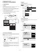
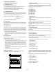
3.1. Soft switch mode
Used to change the soft switch settings.
The soft switch which is stored internally is set by using the keys.
The available soft switches are SW-A1 to SW-P7.
The content of soft switches is shown in Soft switch description.
The contents are set to factory default settings.
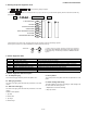
3.2. ROM & RAM check
ROM executes the sum check, and RAM executes the matching test.
The result will be notified with the number of short sounds of the
buzzer as well as by printing the ROM & RAM check list.
Number of short sounds of buzzer 0 → No error
1 → FAX engine ROM error
2 → RAM error
(4Kbytes SRAM or 512Kbytes DRAM)
3.3. Aging mode
The check pattern will be printed sheet by sheet. This operation will be
executed at a rate of one sheet per 5 minutes, and will be ended at a
total of 10 sheets.
3.4. Panel key test
This mode is used to check whether each key operates properly.
Press the key on the operation panel, and the key will be displayed on
the LCD. Therefore, press all keys. At this time, finally press the STOP
key. When the STOP key is pressed, the keys that are not judged as
"pressed" will be printed on the result list.
• LED part of the contact image sensor (CIS) is kept on during the
term from when "START" of the panel test mode to end with the
STOP key.
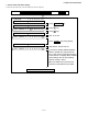
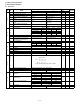
3.5. Check pattern
Check patterns are printed on one sheet. Printing performance:The
following 4 items are checked.
• Print area:Checks that the print area is reserved.
• Nozzles:When checking the nozzle, make sure at least 1 line is
printed in each block: all the blocks of horizontal black bars and the
black line patterns in (B) and (C) ((B):16 patterns, (C):13 patterns).
(Note: If the nozzle (A) is not spraying properly, checking the area
(B) and (C) may be difficult (or may not be printed at all). In this
case, print again.
• Vertical align:Checks that the straight vertical line is drawn instead
of crooked line.
• Skew:Checks the skew of the recording paper.
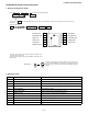
Detailed of check patterns
(1)Top skew (2)Nozzle test (3)Vertical lines (4)Bottom skew
(5)Top margin (6)Left margin (7)Bottom margin
3.6. Signal send mode
This mode is used to send various signals to the circuit during FAX
communication. Every push of START key sends a signal in the follow-
ing sequence. Moreover, the signal sound is also output to the speaker
when the line monitor of the soft switch is on.
[1] No signals
[2] 9600BPS (V.29)
[3] 7200BPS (V.29)
[4] 4800BPS (V.27ter)
[5] 2400BPS (V.27ter)
[6] 300BPS (FLAG)
[7] 2100Hz (CED)
[8] 1100Hz (CNG)
3.7. Memory clear
This mode is used to clear the backup memory and reset to the default
settings.
3.8. Shading mode
The mode is used for the shading compensation. For reading, set up
the special original paper. (Refer to page 8-3)
The compensation memorizes the reference data of white and black
for reading.
Moreover, the memorized data is not erased even if memory clear
mode is executed.
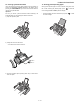
3.9. Auto feeder mode
In this mode, a document is inserted and discharged to check the auto
feed function.
After this mode is started, set a document, and the document feed will
be automatically tested.
3.10. Entry data send
This mode is used to send the registered data to another machine and
make the other machine copy the registered content.
Before sending in this mode, it is necessary to set the other machine
at the entry data receive mode.
The following, information will be sent to the remote machine:
1. Telephone list data
2. Sender register data
3. Optional setting content
4. Soft switch content
5. Junk fax number
6. Recording setting list data
3.11. Entry data receive
In this mode, the registered data sent from the other machine is receiv-
ed and the received data is registered in the machine. When this mode
is used for receiving, the other machine must be in the entry data send
mode.
After receiving is completed, the following lists are printed.
1. Telephone list data
2. Sender register list (*)
3. Optional setting list (*)
4. Soft switch content
5. Junk fax number list (*)
6. Recording setting list data (*)
(*): Refer to SETUP LIST
0 1 2 3 4 5 6 7 8 9 10 11 12 13 14 15 16 17 18 19 20 21 22 23 24 25 26 27 28 29 30
(7)
(5)
(A)
(B)
(C)
(6)
(1)
(2)
(3)
(4)