
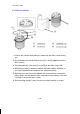
Specifications
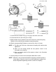
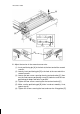
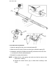

7. Put the bead of the blue wire [3] in slot [A] on the Allen screw side.
8. Put the bead of the silver wire [4] in slot [B].
9. Wind the blue wire [3] clockwise one and a half times around the pulley.
Wind the silver wire [4] once clockwise around the pulley.
10. Slide the omega clamp [C] down to secure all the wires as shown.
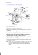
NOTE: a) The blue and silver wires alternate on the pulley with the blue wire
uppermost.
b) Wires are not wound around the two grooves shown in the
illustration (rear view [D]).
c) Wires are wound around all the grooves shown in the illustration
(front view [E]).
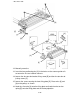
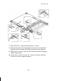
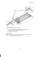
11. Set the pulley on the drive shaft and tighten both Allen screws.
NOTE: Maintain 1 mm of clearance between the pulley and the bushing as
shown above. Place the scale (1 mm thick) between the pulley and
the bushing before tightening the Allen screws on the pulley.
[3]
[4]
[A]
[B]
[C]
[E]
[D]
[D]
[1]
[2]
[3]
[4]
1 December 1990
5-16