
Specifications

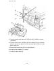
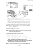
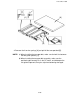

13. Connect the optic cable connector (2P/Black) [A] to CN206 on the inter-
face board.
14. Connect the dc harness (4P/White) [B] to the optional harness connector
[C]; then, connect the optional harness connector [D] to CN102 on the dc
power supply unit.
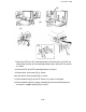
15. Secure the grounding wire [E] to the right side plate.
16. Install the angle stopper [F] (2 screws).
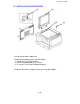
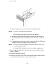
17. Install the original table [G].
[A]
[D]
[E]
[B]
[C]
[G]
[F]
1 December 1990
8-28