
Specifications
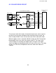


7.2 BIN DRIVE CIRCUIT
To turn on the bin drive motor, the interface board sends drive signals to the
drive IC on the sorter main board. After receiving the drive signals, the drive
IC either raises CN102-8 or CN102-9 to +12 volts. This turns on the bin drive
motor which respectively moves a bin up or down. The main board monitors
the output of both sorter switches through the data select IC through the
interface board. When either the home position switch or wheel switch is
actuated, CN102-11 or CN102-12 drops to LOW. The interface board outputs
three scan signals to the data select IC. The status of the switches changes
the resulting scan output signal. Using the scan output signal, the copier main
board determines the status of the switch.
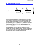
The CPU monitors the on-time of the bin drive motor to detect a malfunction
of the bin drive motor. If the bin drive motor continues to rotate more than
twelve seconds, the CPU stops machine operation.
CN102-1
CN51-1
CN51-2
CN101-3
CN203-1
CN101-4
CN203-2
CN101-5
CN203-3
CN101-6
CN203-10
CN101-7
CN203-4
CN101-8
CN203-5
CN101-9
CN203-6
Sorter Main Board (PCB1)
Interface Board
(PCB6)
CN102-9
Drive
M
Data
Select
IC
Drive
IC
Scan Signal
Scan Output
Clock Pulse
+5V
0V
Home Position Switch
CN102-2
Wheel Switch
T51
T52
T53
T54
CN102-12
CN102-11
CN102-8
Bin
Down
0V
0V
+12V
Up
0V
0V
+12V
+5V
0V
Drive Signal
CN2
1 December 1990
9-10