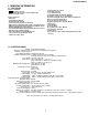
VC-A565U/H965U SERVICE MANUAL S41R7VC-A411U SERVICE MANUAL VIDEO CASSETTE RECORDER VC-A565U VIDEO CASSETTE RECORDER MODELS VC-H965U VC-A565U VC-H965U In the interests of user-safety (Required by safety regulations in some countries) the set should be restored to its original condition and only parts identical to those specified be used. CONTENTS MODELS VC-A565U/H965U 1. 2. 3. 4. 5. 6. 7. 8. 9. 10. 11. 12. Page GENERAL INFORMATION ..................................................................
VC-A565U/H965U IMPORTANT SERVICE NOTES etc.) and measure the AC voltage drop across the resistor. Reverse the AC plug on the set and repeat AC voltage measurements for each exposed part. Any reading of 0.45V rms (this corresponds to 0.3mA rms AC.) or more is excessive and indicates a potential shock hazard which must be corrected before returning the video cassette recorder to the owner.
VC-A565U/H965U NOTES DE SERVICE IMPORTANTES pièces métalliques exposées ayant un parcours de retour au châssis (connexions d’antenne, coffret métallique, tétes de vis, boutons et arbres de commande, etc.) et mesurer la chute de tension CA entre la résistance. Inverser la fiche CA (une fiche intermédiaire non polarisée doit être utilisée à seule fin de faire ces vérifications.) sur l’appareil et répéter les mesures de tension CA pour chaque piéce métallique exposée.
VC-A565U/H965U PRECAUTIONS IN PART REPLACEMENT When servicing the unit with power on, be careful to the section marked white all over. This is the primary power circuit which is live. When checking the soldering side in the tape travel mode, make sure first that the tape has been loaded and then turn over the PWB with due care to the primary power circuit. Make readjustment, if needed after replacement of part, with the mechanism and its PWB in position in the main frame.
VC-A565U/H965U 1.
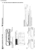
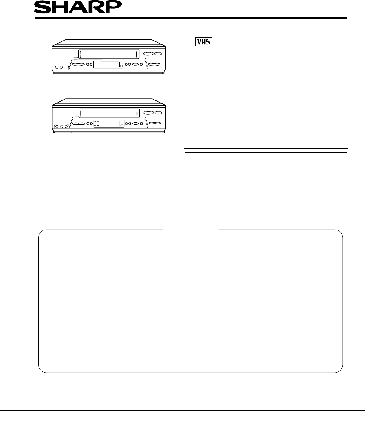
(VC-H965U) POWER button (When pressed to turn on the VCR, POWER LED indicator will light up. When the power is turned off. POWER LED indicator wil turn off.
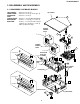
VC-A565U/H965U 2. DISASSEMBLY AND REASSEMBLY 2-1 DISASSEMBLY OF MAJOR BLOCKS TOP CABINET FRONT PANEL OPERATION PWB SHIELD ANGLE MECHANISM/ MAIN PWB : Remove 2 screws 1. : Remove 2 screws 2 and 7 clips 3. : Remove 1 screw 4. TOP CABINET 1 : Remove 1 screw 5 with shield angle. : Remove 1 screw 6, 2 screws 7. Remove 1 screw 8 with antenna terminal cover. Remove 1 screw 9 with top cabinet fix angle.
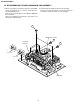
VC-A565U/H965U 2-2 DISASSEMBLING THE MECHANISM/MAIN PWB ASSEMBLY 2. Removing the mechanism and cassette housing. Remove 2 screws 3 fixing the cassette housing to the mechanism, and remove the cassette housing. 1. When removing the mechanism from the main PWB, remove the antenna cover 1 screw 1, and remove the antenna terminal cover. Remove the screw 2 which connecting the PWB and the mechanism. Take out vertically the mechanism so that it does not damage the adjacent parts.
VC-A565U/H965U 2-3 CARES WHEN REASSEMBLING housing. (Conditions: When mechanism and PWB have been installed) INSTALLING THE CASSETTE HOUSING When the cassette housing is installed on the mechanism, the initial setting is essential condition. There are two initial setting methods, namely electrical and mechanical. 1. Electrical initial setting So as to perform initial setting of mechanism execute the Step 1 of Installation of cassette housing.
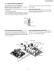
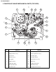
VC-A565U/H965U 3. FUNCTION OF MAJOR MECHANICAL PARTS (TOP VIEW) 17 18 15 10 16 14 1 9 2 11 3 5 7 8 6 No. 4 12 Function 13 No.
VC-A565U/H965U FUNCTION OF MAJOR MECHANICAL PARTS (BOTTOM VIEW) 21 22 25 19 20 23 No. 24 Function No. Function 19 Syncro Gear 23 Clutch lever 20 Master cam 24 Limiter pulley ass’y 21 Capstan D.D.
VC-A565U/H965U 4. ADJUSTMENT, REPLACEMENT AND ASSEMBLY OF MECHANICAL UNITS The explanation given below relates to the on-site general service (field service) but it does not relates to the adjustment and replacement which need high-grade equipment, jigs and skill. For example, the drum assembling, replacement and adjustment service must be performed by the person who have finished the technical courses.
VC-A565U/H965U 4-2 MAINTENANCE CHECK ITEMS AND EXECUTION TIME Perform the maintenance with the regular intervals as follows so as to maintain the quality of machine. Maintained 500 1000 1500 2000 Possible symptom Remarks encountered hrs. hrs. hrs. hrs. Parts Abnormal rotation or significant Guide roller ass’y vibration requires replacement. Sup guide shaft Reverse guide Lateral noises Head occasionally blocked Clean tape contact part with the specified cleaning liquid.
VC-A565U/H965U 4-3 REMOVING AND INSTALLING THE CASSETTE HOUSING Notes: 1. In the case when you use the magnet screw driver, never approach the magnet driver to the A/C head, FE head, and drum. 2. When installing or removing, take care so that the cassette housing control and tool do not contact the guide pin or drum. 3. After installing the cassette housing control once perform cassette loading operation. • Removal 1. In the cassette removing mode, remove the cassette. 2. Unplug the power cord. 3.
VC-A565U/H965U 4-5 REEL DISK REPLACEMENT AND HEIGHT CHECK Notes: 1. When installing the reel disk, take due care so that the tension band ass'y is not deformed and grease does no adhere. 2. Do not damage the Supply main brake ass'y. Be careful so that grease does not adhere to the brake surface. • Removal 1. Remove the cassette housing control assembly. 2. Remove the Supply/Take-up main brake ass'y. 3. Pull the tension band out of the tension arm ass'y. 4. Remove the reel disk.
VC-A565U/H965U Note: Whenever replacing the reel disk, perform the height checking and adjustment. Reel disk height adjusting jig Master plane 10 ± 0.2mm Notes: 1. Hold the torque gauge by hand so that it is not moved. 2. Do not keep the reel disk in lock state. Do not allow longtime measurement. 4-7 CHECKING AND ADJUSTMENT OF TAKEUP TORQUE IN REWIND MODE Mechanism chassis Reel disk • Remove the cassette housing control assembly.
VC-A565U/H965U Notes: 1. Hold the torque gauge by hand so that it is not moved. 2. Do not keep the reel disk in lock state. Do not allow longtime measurement. 4-9 CHECKING AND ADJUSTMENT OF TAKEUP TORQUE IN VIDEO SEARCH REWIND MODE 4-8 CHECKING AND ADJUSTMENT OF TAKEUP TORQUE IN RECORD/PLAYBACK MODE • After short-circuiting between TP803 and TP802 provided at operation PWB, plug in the power cord. • Remove the cassette housing control assembly.
VC-A565U/H965U 4-10 CHECKING THE VIDEO SEARCH REWIND BACK TENSION • Remove the cassette housing control assembly. • After short-circuiting between TP803 and TP802 provided at operation PWB, plug in the power cord. Tension gauge 900 - 1,200gf Pinch roller • Checking 1. After pressing the play button, press the rewind button, and set the video search rewind mode. 2.
VC-A565U/H965U 2. Visually check to see if the position of the tension pole is within the 0 ± 0.2mm from the left side line. Tension pole adjustment driver adjusting direction CW CC W Standard A = 0 ± 0.2mm A Tension pole adjustment driver Make the adjustment with the beginning of a T-120 tape. Figure 4-16. Figure 4-13. At left side from the reference line. (A). 4-13 CHECKING AND ADJUSTMENT OF RECORD/PLAYBACK BACK TENSION • Remove the cassette housing control assembly.
VC-A565U/H965U • Adjustment 1. If the indication of torque cassette meter is lower than the setting, shift the tension spring engagement to the part A. 2. If the indication of torque cassette meter is higher than the setting, shift the tension spring engagement to the part B. A • Checking the brake torque at the take-up side Torque gauge Tension arm B CW CCW Take-up reel disk Tension spring CCW: 4.41 ± 1.5mN⋅m (45 ± 15gf⋅cm) CW: 4.12 ± 1.2mN⋅m (42 ± 12gf⋅cm) Figure 4-18.
VC-A565U/H965U 3. Align the left end of gear of A/C head arm with the punched mark of chassis, tentatively tighten the screws 1 so as to ensure smooth motion of A/C head arm. Tightening torque must be 0.45 ± 0.05N·m (4.5 ± 0.5kgf·cm). 4-15 REPLACEMENT OF A/C (AUDIO/CONTROL) HEAD 1. Remove the cassette housing control assembly. 2. In unloading state unplug the power cord. • Removal 1. Remove the screws 123, Tilt screw. 2. Unsolder the PWB fitted to the A/C head. Notes: 1.
VC-A565U/H965U 4-16 A/C HEAD HEIGHT ROUGH ADJUSTMENT 4-17 ADJUSTMENT OF TAPE DRIVE TRAIN 1. Tape run rough adjustment 1 Remove the cassette housing control assembly. 2 After shortcircuiting between TP803 and TP802 provided at operation PWB, plug in the power cord. 3 Check and adjust the position of the tension pole. (See 4-12.) 4 Check and adjust the video search rewind back tension. (See 4-10.) 5 Connect the oscilloscope to the test point for PB ATR signal output (TP201).
VC-A565U/H965U Notes: 1. Previously set the tracking control in the center position, and adjust the ATR signal waveform to maximum with X value adjustment nut. Thereby the tape run rough adjustment is facilitated. 2. Especially the outlet side ATR signal waveform must have higher flatness. Figure 4-27. 2. Adjustment of A/C head height and azimuth 1 Perform the initial setting of A/C head position by the method stated in "4-15 Replacement 3". 2 Connect the oscilloscope to the audio output terminal.
VC-A565U/H965U 3 Next, press the tracking button (+), (–) and change the ATR signal waveform from max to min and from min to max. At this time adjust the height of supply and take-up side guide roller with the adjustment driver (JiGDRiVERH-4) so that the ATR signal waveform changes nearly parallel. 4 If the tape is lifted or sunk from the helical lead surface, the PB ATR signal waveform appears as shown in Figure 4-30.
VC-A565U/H965U 4-19 REPLACEMENT OF DRUM D.D. MOTOR 4-18 REPLACEMENT OF THE CAPSTAN D.D. (DIRECT DRIVE) MOTOR 1. Set the ejection mode. 2. Withdraw the main power plug from the socket. • Remove the mechanism from the main PWB (refer to 22 item 1 When removing the mechanism from the main PWB ). • 1. 2. 3. 4. 5. • Removal (Follow the order of indicated numbers.) 1. Remove the reel belt 1. 2. Remove the slow brake lever 2. 3. Remove the three screws 3. Notes: 1. In removing the D.D.
VC-A565U/H965U 4-20 REPLACING THE UPPER AND LOWER DRUM ASSEMBLY 4-21 ASSEMBLING OF PHASE MATCHING MECHANISM COMPONENTS • Replacement (Perform in the numerical order) 1 Remove the motor as stated in 4-19 D.D. motor replacement. 2 Remove the drum earth brush ass’y 2. 3 Remove the upper and lower drum assembly from main chassis 1. 4. Remove the drum FFC holder 3. • Assemble the phase matching mechanism components in the following order. 1. Assemble the reverse guide lever and pinch drive cam. 2.
VC-A565U/H965U 1. Make sure that the loading arm T and S are at the PhaseMatching point as shown below a . 2. Fix the shifter position setting part to the roading arm T position setting part as shown in figure .b 3. Make sure tension arm not run on the shifter as shown in figure c . 4-22 INSTALLING THE SHIFTER Drum Capstan D.D. motor Limiter pully (Bottom side of mechanism chassis) Figure 4-36.
VC-A565U/H965U 4-23 INSTALLING THE MASTER CAM (AT REAR SIDE OF MECHANISM CHASSIS) 4-24 REPLACEMENT OF LOADING MOTOR • Removal 1. Make sure beforehand that the shifter is at initial position. 2. Place the master cam in the position as shown below. E-ring Apply grease *Apply grease to the tip as well. Worm gear Apply grease Loading motor. Leading connect gear. Apply grease Worm wheel gear. Red Apply grease Wire + : Red - : White Insert Figure 4-38-1. L-M-Block.
VC-A565U/H965U 4-25 ASSEMBLY OF CASSETTE HOUSING 1. Proof lever Proof lever spring and Holder R MSPRD0215AJFJ *Proof lever spring fixing direction designated. Figure 4-41. 2. Frame R, Frame L, Drive Arm R, Drive Arm L, Upper Plate. LANGF9661AJFW Top surface should be free from scratches or soil.
VC-A565U/H965U 5. ELECTRICAL ADJUSTMENT Notes: • Before the adjustment: Electrical adjustments discussed here are often required after replacement of electronic components and mechanical parts such as video heads. Check that the mechanism and all electric components are in good working condition prior to the adjustments, otherwise adjustments cannot be completed.
VC-A565U/H965U SERVO CIRCUIT ADJUSTMENT 5-2 ADJUSTMENT OF FV (False Vertical Sync) OF STILL PICTURE 5-1 ADJUSTMENT OF HEAD SWITCHING POINT Measuring instrument Color TV monitor Mode Playback still Cassette Self-recorded tape (SP mode) (See Note below 2) Measuring instrument Dual-trace oscilloscope Mode Playback Cassette Alignment tape (VROEFZHS) Control Tracking control buttons(+) or (–) Test point VIDEO OUT jack to CH2 TP202 (Sig.
0 19.812 CA/END CS/EJ 1 1 1 1 Mode detection inside S sensor Open S sensor Close 0 0 EJ 10.354 12.
REC/PLAY 33 VSF End Set capstan motor to search speed. Press FF key. PLAY Unloading End YES Is take-up reel sensor signal outputted ? Picture appears. Capstan motor turns counterclockwise. Press REC/PLAY key. STOP NO Slow brake pressing STILL STOP Unloading End YES Is take-up reel sensor signal outputted ? End Stop loading motor. Cam switch is at VSR position. Press pinch roller. Turn loading motor counterclockwise. Cam switch is at PU1 position.
Brake function FF/REW operation FF/REW STOP 34 End Loading motor stops. Cam switch is at Stop position. Stop capstan motor. Loading motor turns counterclockwise. Press STOP key. FF/REW End Turn capstan motor in normal or reverse direction, after the remaining tape has been detected. Press FF/REW key. STOP Cassette eject Tape unloading CASSETTE EJECT End Capstan motor stops. Loading motor stops. Cam switch is at Eject position. Loading motor turns clockwise.
NO 35 The cassette tape is presumably damaged. YES Is the pulse NO outputted from reel sensor ? YES Are idler wheel NO ass’y and reel disk in mesh ? YES Does capstan NO motor turn in FF (or REW) direction ? YES Is master cam at FF position ? Replace the reel sensor. Replace the idler ass’y. Replace the capstan motor. YES Are Vco 12V and Vcc 5V applied ? Loading motor control system in trouble.
NO NO 36 Check main PWB. YES Is pulse outputted NO from reel sensor ? YES Is supply reel disk NO winding torque normal ? YES Are idler wheel NO ass’y and supply reel disk in mesh ? YES Master cam shifting to VSR position ? Press REW key. YES Is Playback function normal ? Replace reel sensor. Replace limiter pulley ass’y. Replace idler gear ass’y. Go to 2. REC/ PLAY FAILURE routine. Go to 2. REC/ PLAY FAILURE routine. 3. WINDING FAILURE AT VSR Replace loading motor block.
Check drive system’s gears for damage. Replace damaged gear with new one. • Reel disk • Limiter pulley ass’y • Idler wheel ass’y NO Turn capstan motor by hand. Unusual sound heard ? NO Drive system out of contact with any part on main PWB ? YES Thrust gap found at reel disk ? YES Is reel disk height as specified ? 4-ii) Unusual sound in FF/REW mode YES YES NO NO Replace capstan motor. Rearrange the parts on main PWB. Check reel disk and main chassis. And replace defective parts.
Replace IC901. Check whether the secondary side photocoupler circuit operates normally. YES Check whether the primary side photocoupler output control functions normally. YES Check the circuit and replace parts. (IC901, IC903, etc.) Check the circuit and replace parts. (IC901, IC903, Q902, T901, etc.) NO NO When the output voltage fluctuates. FLOW CHART NO.3 Check for short-circuiting of rectifying diode and circuit in each rectifying circuit of secondary circuit.
FLOW CHART NO.6 39 YES Replace loading motor. YES Does pin(10) of P701 go from 2.5V to 4.2V when the cassette tape is inserted. NO NO NO Check line pin(72) of IC701 and all the way up thru to pin(10) of P701. Check line start sensor and all the way up thru to pin(67) of IC701. Check start sensor shutter. Check line between at remote control receiver thru to pin(4) of IC701. A cassette tape is not take in.
Replace cassette cam, gear, etc. YES Does the loading motor run? YES Does pin(10) of P701 go from 2.5V to 0.8V when veel pules has beer input. YES Are pulses applied at pin(2) of IC701 when the take-up reel disk is turning? YES NO NO NO Does the take-up reel disk turn when NO the capstan motor is running? YES NO Replace loading motor. Check pin(72) of IC701. Check take-up reel sensor and all the way up thru to IC701. Check reel disk and reel drive unit. See FLOW CHART NO.11.
FLOW CHART NO.13 NO NO NO Check AT 12V line. Check between pin(25) of IC701 and all the way up to pin(12) of P701. Check PC 5V line. Check IC701. Replace IC701. YES Is V-H.SW.P pulse given out of pin(18) of IC701? YES Is drum PG signal given out of pin(47) of IC701? YES Is drum PG signal given out of pin(11) of P701. NO NO NO Check IC701. Check line between pin(11) of P701 and all the way up thru to pin(47) of IC701. Check or replace drum motor. YES Check pin(12) of P701.
Check drum PG/FG signal line. YES 42 Does the IC706 operate normally? YES Is the drum control voltage applied to pin(2) of IC701. YES Is the drum-error at pin(29) of IC701 present? YES YES NO NO Is the head switching pulse at pin(18) NO of IC701 present? NO Is there drum PG/FG signal at pin(47). In PB mode Replace drum motor. Is pin(25) of IC701 in high impedance? YES Check lines between pin(29) of IC701 and pin(12) of P701. Replace IC701. See FLOW CHART NO.14. YES Is there 14.
YES Adjust the height of the A/C head. YES Does A/C head NO operate normally? NO Does PB CTL signal appear at pin(58) of IC701? 1 Only PB mode inoperative Replace A/C head. Replace IC701. NO Is there CAPERROR at pin(28) of IC701? YES Check capstan motor unit and/or replace. Check peripheral circuit of X701. NO Is there 14.318MHz YES oscillation at pin (32) and (33) of IC701? YES Are REC and/or PB mode inoperative? Capstan servo does not function. FLOW CHART NO.
FLOW CHART NO.17 Check the line between pin(52) of IC201 and pin(40) of IC701. NO 44 Check the AT 5V line. NO Is 5V applied to the pin(42) of IC701? NO NO Check the PC 5V line. NO Check Q251 periphery. Check the line between pins(63) and (62) of IC201 and pins(64) and (65) of IC701.
YES Check the pins(13) and (14) of IC201 peripheral circuit. (R201, R202, C203) Check between the pins(24) and (23) of IC201. (Check C210.) Is CCD control voltage approx. 5V applied normally to the pin(37) from the pin(57) of IC201? Is clock signal (approx. 7.16 MHz/0.5 Vp-p) for CCD applied normally to the pin(44) from the pin(69) of IC201? YES Is voltage 5V applied to the CCD section power terminal pin(36) of IC201? NO Is luminance signal (approx. 0.
NO NO Replace IC201. YES Is luminance signal (approx. 0.5 Vp-p) input to the pin(23) of IC201? YES NO NO Is luminance signal (approx. 0.5 Vp-p) input to the pin(26) of IC201? YES Is luminance signal (approx. 0.5 Vp-p) input to the pin(42) of IC201? YES Is luminance signal (approx. 0.5 Vp-p) input to the pin(19) of IC201? YES Is the luminance signal (approx. 0.
pin(14) pin(9) pin(48) Rear input terminal Tuner audio terminal 47 NO NO NO NO NO NO NO Check line between X501 and pin(45) of IC651. NO Is Sub carrier signal (3.58MHz, about 900mVp-p) input to pin(45) of IC651? Check line between pin(36) of IC651 and pin(61) of IC701. Check line between pins(43), (42) of IC651 and pins(12), (13) of IC701. Check the regulator circuit of Hi-Fi 5V and PC 9V. Check the peripheral circuit of front input terminal.
FLOW CHART NO.26 Check the line between the pin(11) of IC201 to the pin(62) of IC651. YES Is audio signal output to the pin(11) of IC201? YES Is it possible to confirm the audio signal (PB EQ) on the pin(100) of IC201? Linear audio playback is impossible. (Hi-Fi E-E mode is normal). NO NO NO Replace IC201. YES Check the periphery of pin(99) of IC201. NO Is the pin(99) of IC201 in "L" level? Readjust the A/C head height. Replace the AC head.
VC-A565U/H965U -MEMO- 49
VC-A565U/H965U VC-A565U/H965U 8.
VC-A565U/H965U VC-A565U/H965U SIGNAL FLOW BLOCK DIAGRAM(A565U) 52~53
VC-A565U/H965U VC-A565U/H965U SIGNAL FLOW BLOCK DIAGRAM(A965U) 54~55
VC-A565U/H965U POWER CIRCUIT BLOCK DIAGRAM 56
VC-A565U/H965U SCHEMATIC DIAGRAM • The indicated voltages in the following diagram are measured with an SSVM, upon receiving color bars (400 Hz sound signal) in either the record mode or the play mode voltage is indicated as follows. 4.0 . . . . Record mode (SP) (4.0) . . . . PB mode (SP) 4.0 . . . . LP mode 4.0 . . . . EP mode IMPORTANT SAFETY NOTICE: PARTS MARKED WITH " å" ( ) ARE IMPORTANT FOR MAINTAINING THE SAFETY OF THE SET.
VC-A565U/H965U VC-A565U/H965U 9. SCHEMATIC DIAGRAM AND PWB FOIL PATTERN MAIN CIRCUIT(1) J I H G F E D C B A 1 2 * VOLTAGE MEASUREMENT MODE PB .......... Parentheses ( ) REC .......
VC-A565U/H965U VC-A565U/H965U MAIN CIRCUIT(2) J I H G F E D C B A 1 2 * VOLTAGE MEASUREMENT MODE PB .......... Parentheses ( ) REC .......
VC-A565U/H965U VC-A565U/H965U MAIN CIRCUIT(3) J I H G F E D C B A 1 2 * VOLTAGE MEASUREMENT MODE PB .......... Parentheses ( ) REC .......
VC-A565U/H965U VC-A565U/H965U MAIN CIRCUIT(4) J I H G F E D C B A 1 2 * VOLTAGE MEASUREMENT MODE PB .......... Parentheses ( ) REC .......
VC-A565U/H965U OPERATION CIRCUIT J I H G F E D C B A 1 2 * VOLTAGE MEASUREMENT MODE PB .......... Parentheses ( ) REC .......
VC-A565U/H965U PWB FOIL PATTERN OPERATION PWB J I H G F E D LCD PWB C B A 1 2 3 4 5 6 67 7 8 9 10
VC-A565U/H965U VC-A565U/H965U MAIN PWB J I H G F E D C B A 1 2 3 4 5 6 7 8 9 10 11 68~69 12 13 14 15 16 17 18 19 20
VC-A565U/H965U -MEMO- 70
VC-A565U/H965U Part No. ★ Description 10. REPLACEMENT PARTS LISTCode Ref. No. Ref. No. No. ★ Description 10.PartLISTE DES PIECES Code PARTS REPLACEMENT CHANGE DES PIECES Many electrical and mechanical parts in video cassette recorder have special safety-related characteristics. These characteristics are often not evident from visual inspection nor can the protection afforded by them necessarily be obtained by using replacement components rated for higher voltage, wattage, etc.
VC-A565U/H965U Ref. No. Q968 Q7781 ★ Part No. VS2SA1530ARS1 VS2SC3052EF-1 Description V 2SA1530AR V 2SC3052EF Code Ref. No.
VC-A565U/H965U Ref. No. Part No.
VC-A565U/H965U Ref. No. Part No.
VC-A565U/H965U Ref. No. Part No.
VC-A565U/H965U Ref. No. Part No.
VC-A565U/H965U Ref. No. Part No. ★ Description Code Ref. No.
VC-A565U/H965U 11. EXPLODED VIEW OF MECHANICAL Ref. PARTS No. Part No. ★ Description Code ★ Part No. Ref. No.
VC-A565U/H965U Ref. No. Part No. ★ Description Code Ref. No. CASSETTE HOUSING CONTROL PARTS Part No.
VC-A565U/H965U Ref. No. Part No. CABINET PARTS ★ Description Ref. No. Code ★ Part No.
VC-A565U/H965U Ref. No. PANEL Part No. ★ Description FRONT PARTS(VC-A565U) Code Ref. No. Part No.
VC-A565U/H965U Ref. No. PANEL Part No. ★ Description FRONT PARTS(VC-H965U) Ref. No. Code ★ Part No.
VC-A565U/H965U Part No. ★ Description 12. PACKING OF THE SET Ref. No. Code Ref. No. Part No. ★ Description ■ Setting position of the Knobs RF conv. CH. preset at "3" channel Accessories TiNS-4085AJZZ Instruction Book ★ Dry Battery RRMCG1237AJSB Infrared Remote Control Unit ★ SPAKP0114AJZZ Foam Bag QCNW-8614AJZZ 75 ohm Coaxial Cable ★ SPAKX1152AJZZ Packing Foam.
VC-A565U/H965U Ref. No. Part No. ★ Description Ref. No. Code ★ Part No. Description Code COPYRIGHT © 2002 BY SHARP CORPORATION ALL RIGHTS RESERVED. No part of this publication may be reproduced, stored in a retrieval system, or transmitted in any form or by any means, electronic, mechanical, photocopying, recording, or otherwise, without prior written permission of the publisher.