
Service manual


6
VE-CG30U
VE-CG40U
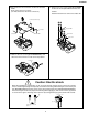
4. DISASSEMBLY OF THE SET
4-1. DISASSEMBLY OF THE SET
Note:
Before removing the cabinet, turn off the power supply, and ascertain that the battery have been removed.
5.
1.
3.
4.
2.
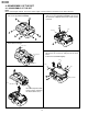
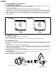
Remove the five screws ((a)LX-HZ0063TAFF) and
two screws ((h)XiPSF17P04000).
a
a
a
a
a
h
h
Open the media lid and jack cover, and then open the
back cabinet turning it.
Jack cover
Back cabinet
Media lid
FFC
Disconnect the connector and pull out the FFC.
LCD unit
FFC
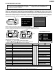
After removing the one screw ((f)XiPSF17P03000)
and one screw ((g)XiPSN17P02000), disconnect
the connector and pull out the FFC to take out the
LCD unit.
CCD PWB
FFC
FFC
FFC
After removing the three screws ((f)XiPSF17P03000),
disconnect the connector and pull out the three
FFCs.
Pull out the CCD PWB slightly.
Be sure to keep the media
lid open when attaching
the back cabinet ass'y.