
System information


Interfaces and Connectors
EPM-15 Reference Manual 35
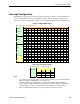
Null Modem
The following diagram illustrates a typical DB9 to DB9 RS-232 null modem adapter.
System 1 <--> System 2
Name Pin Pin Name
------------------------------------
TX 3 <--> 2 RX
RX 2 <--> 3 TX
RTS 7 <--> 1 DCD
CTS 8
DSR 6 <--> 4 DTR
DCD 1 <--> 7 RTS
8 CTS
DTR 4 <--> 6 DSR
Pins 7 and 8 are shorted together on each connector. Unlisted pins have no connection.