
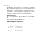
System information


EIDE Hard Drive / CD-ROM Interfaces
32 – Reference VSBC-6 Reference Manual
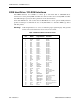
EIDE Hard Drive / CD-ROM Interfaces
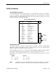
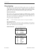
Two EIDE interfaces are available to connect up to four hard disk or CD-ROM drives.
Connector J17 is the primary IDE controller and connector J16 is the secondary IDE controller.
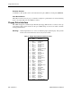
Use CMOS Setup to specify the drive parameters of the attached drives.
Some older IDE drivers, such as those that are PIO Mode 0-1, do not operate reliably with this
product. VersaLogic recommends the use of only PIO Mode 2-3 and Ultra DMA type drives
with this product.
Warning! Cable length must be 18" or less to maintain proper signal integrity. The grounds
in this connector should not be used to carry motor current.
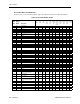
Table 9: EIDE Hard Drive Connector Pinout
J16, J17
Pin
Signal
Name
EIDE
Signal Name Function
1 HRST* Host Reset Reset signal from CPU
2 Ground Ground Ground
3 IDE7 DATA 7 Data bit 7
4 HD8 DATA 8 Data bit 8
5 HD6 DATA 6 Data bit 6
6 HD9 DATA 9 Data bit 9
7 HD5 DATA 5 Data bit 5
8 HD10 DATA 10 Data bit 10
9 HD4 DATA 4 Data bit 4
10 HD11 DATA 11 Data bit 11
11 HD3 DATA 3 Data bit 3
12 HD12 DATA 12 Data bit 12
13 HD2 DATA 2 Data bit 2
14 HD13 DATA 13 Data bit 13
15 HD1 DATA 1 Data bit 1
16 HD14 DATA 14 Data bit 14
17 HD0 DATA 0 Data bit 0
18 HD15 DATA 15 Data bit 15
19 Ground Ground Ground
20 NC NC No connection
21 NC NC No connection
22 Ground Ground Ground
23 HWR* HOST IOW* I/O write
24 Ground Ground Ground
25 HRD* HOST IOR* I/O read
26 Ground Ground Ground
27 NC NC No connection
28 HAEN ALE Address latch enable
29 NC NC No connection
30 Ground Ground Ground
31 HINT HOST IRQ14 IRQ14
32 XI16* HOST IOCS16* Drive register enabled
33 HA1 HOST ADDR1 Address bit 1
34 NC NC No connection
35 HA0 HOST ADDR0 Address bit 0
36 HA2 HOST ADDR2 Address bit 2
37 HCS0* HOST CS0* Reg. access chip select 0
38 HCS1* HOST CS1* Reg. access chip select 1
39 NC NC No connection
40 Ground Ground Ground