
System information


Ethernet Interface
38 – Reference VSBC-6 Reference Manual
Ethernet Interface
The VSBC-6 features an industry-standard Ethernet interface based on the SMC LAN
LAN91C96 Interface Chip. While this interface is not NE2000 compatible, the SMC 9000 series
is widely supported. Drivers are readily available to support a variety of operating systems such
as QNX, VxWorks and other RTOS vendors. Win95/98/NT ship with built-in support for this
Ethernet interface. The drivers load automatically when the operating system is installed.
H
ARDWARE
C
ONFIGURATION
Jumper V6[3-4] is used to select the base I/O address for the Ethernet interface, and jumper
V6[1-2] is used to select the Ethernet media you will be using. Select the twisted pair interface if
you want to connect a twisted pair cable to the RJ45 connector. Select the AUI interface if you
want to attach an external transceiver or Media Attachment Unit (MAU). This allows use of
thick or thin coax cable, or fiber optic media to be used.
See page 21 for jumper configuration details.
Note! Use of the AUI interface requires connection of +12V power to the VSBC-6.
S
OFTWARE
C
ONFIGURATION
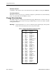
The CMOS Setup screen is used to define the base address and the IRQ line used by the Ethernet
interface, or to enable/disable the device. When disabled, the ethernet interface is "parked" at I/O
addresses 180h – 18Fh and it does not use any interrupts.
E
THERNET
C
ONNECTORS
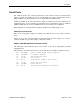
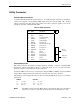
Table 15: RJ45 Ethernet Connector
J3
Pin
Signal
Name Function
1 T+ Transmit Data +
2 T– Transmit Data –
3 R+ Receive Data +
4 NC No Connection
5 NC No Connection
6 R– Receive Data –
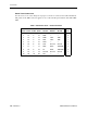
Table 16: AUI Ethernet Connector
J2
Pin
Signal
Name Function
1 CD– Collision Detect –
2 CD+ Collision Detect +
3 TX– Transmit Data –
4 TX+ Transmit Data +
5 GND Ground
6 GND Ground
7 RX– Receive Data –
8 RX+ Receive Data +
9 +12V +12V Power
10 GND Ground