
System information

Analog Input
40 – Reference VSBC-6 Reference Manual
Analog Input
The VSBC-6 "–r" models employ a multi-range, 12-bit A/D converter which will accept up to
eight single-ended input signals. The converter features fast 6 microsecond conversion time, with
channel independent input ranges of 0 to +5V, ±5V, 0 to +10V, and ±10V.
H
ARDWARE
C
ONFIGURATION
There are no jumpers associated with the analog input circuitry.
E
XTERNAL
C
ONNECTIONS
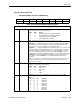
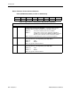
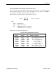
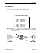
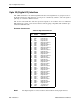
Single-ended analog voltages are applied to connector J10 as shown in the table below.
Table 17: Analog Input Connector
J10
Pin
Signal
Name Function
1 ADCH0 Channel 0 Analog Input
2 ADCH1 Channel 1 Analog Input
3 ADGND Analog Ground
4 ADCH2 Channel 2 Analog Input
5 ADCH3 Channel 3 Analog Input
6 ADGND Analog Ground
7 ADCH4 Channel 4 Analog Input
8 ADCH5 Channel 5 Analog Input
9 ADGND Analog Ground
10 ADCH6 Channel 6 Analog Input
11 ADCH7 Channel 7 Analog Input
12 ADGND Analog Ground
Note! Connector J10 also includes signals for the Opto 22 interface.
Warning! All analog inputs are fault protected to ±16V (board power on or off). Exceeding
these maximums can cause permanent damage to the A/D converter circuitry.
Such damage is not covered under warranty.
C
ALIBRATION
There are no calibration adjustments. Calibration, if desired, is accomplished by mathematical
transformation in software.